Method of error correction

An error correction and error technology, which is applied in the field of coordinate positioning equipment to measure workpieces, can solve problems such as accelerometer drift and noise, unreliable calibration, etc.

Inactive Publication Date: 2009-05-06
RENISHAW PLC
View PDF5 Cites 15 Cited by
  • Summary
  • Abstract
  • Description
  • Claims
  • Application Information

AI Technical Summary

Problems solved by technology

[0013] The drawback with both of the above methods is that accelerometer drift and noise cause problems when trying to correct for low frequency errors (typically 0-5Hz) and thus make the corrections unreliable

Method used


Image

  • Method of error correction
  • Method of error correction
  • Method of error correction

Examples


Embodiment Construction

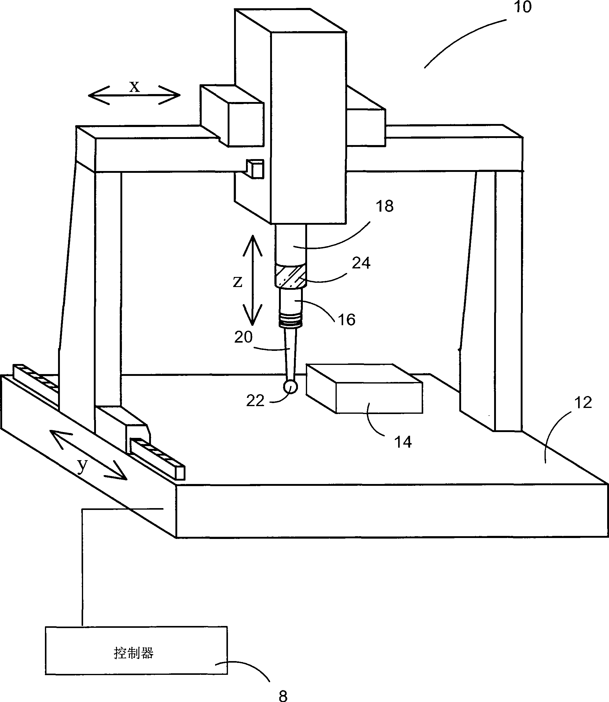
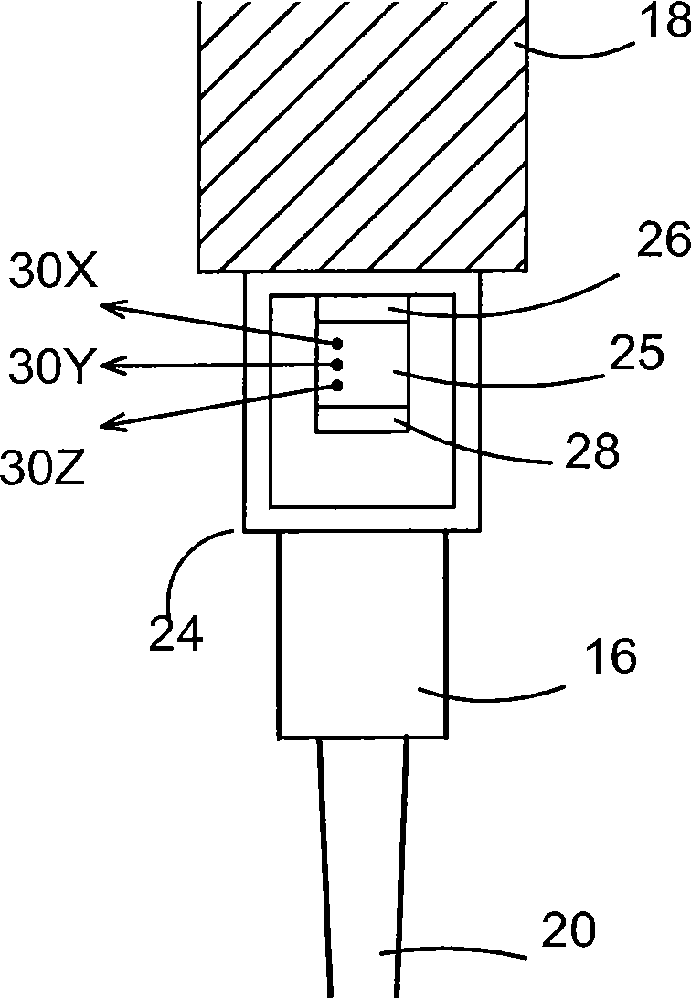
[0060] figure 1 The illustrated coordinate measuring machine (CMM) 10 includes a table 12 on which a workpiece 14 to be measured is placed. This is preferably done by robotic means (not shown) which places a series of substantially identical workpieces from the production line in at least nominally the same position and orientation on the table. An analog probe 16 having a deflectable stylus 20 with a workpiece contact tip 22 is mounted on the main shaft 18 of the instrument, although other types of probes (including contact trigger probes) may also be used. The spindle and probe are moved together in the x, y and x directions by computer-controlled x, y and z drives. The x, y and z scales (including counters for the output scale) show the instantaneous coordinates of the three-dimensional position of the spindle 18 on which the probe 16 is mounted. The signal from the probe 16 representing the deflection of the probe stylus 20 is combined with the CMM's x, y, z scale readin...


PUM


Abstract

A method of error correction of workpiece measurements using coordinate measuring machines has the steps of measuring the workpiece, determining the repeatable measurement errors from a predetermined error function, look-up table or map, measuring at least a function of the acceleration and calculating the unrepeatable measurement errors as the workpiece is measured, combining the repeatable and non repeatable errors to determine the total errors and using the total errors to correct the measurements of the workpiece.

Description

technical field [0001] The invention relates to the measurement of workpieces by means of coordinate positioning equipment. Coordinate positioning equipment can include coordinate measuring machines (CMMs), machine tools, manual coordinate measuring arms, and inspection robots. In particular, the invention relates to correcting errors in workpiece measurements. Background technique [0002] After a workpiece is produced, it is common practice to inspect it on a coordinate measuring machine (CMM) that has a spindle (quill) to which probes are mounted to move along three orthogonal directions x, y and z The probe is driven within the workspace of the instrument. It is also common practice to inspect workpieces with probes mounted on the machine tool as part of process control. [0003] Inaccuracies caused by dynamic deflection of the instrument can be reduced by slowing down the instrument speed and causing the probe to travel very slowly when the probe contacts the workpie...

Claims


Application Information

Patent Timeline
Patent Type & Authority Applications(China)
IPC IPC(8): G01B21/04
CPCG01B21/045
Inventor 若弗雷·麦克法兰凯维恩·巴里·乔纳斯詹姆斯·弗格斯·罗伯逊尼古拉斯·约翰·韦斯顿赖清河
Owner RENISHAW PLC
Why Eureka
Try Eureka