Continuous variable air valve lift apparatus

A valve lift, variable technology, applied in the direction of valve device, internal combustion piston engine, engine components, etc., can solve the problems such as non-continuously variable, invariable valve lift, etc.

Active Publication Date: 2009-05-13
CHERY AUTOMOBILE CO LTD
View PDF0 Cites 29 Cited by
  • Summary
  • Abstract
  • Description
  • Claims
  • Application Information

AI Technical Summary

Problems solved by technology

[0003] The technical problem to be solved by the present invention is to provide a continuously variable valve lift device adapted to different working conditions of the engine to solve the problem that the v

Method used


Image

  • Continuous variable air valve lift apparatus
  • Continuous variable air valve lift apparatus
  • Continuous variable air valve lift apparatus

Examples


Embodiment Construction

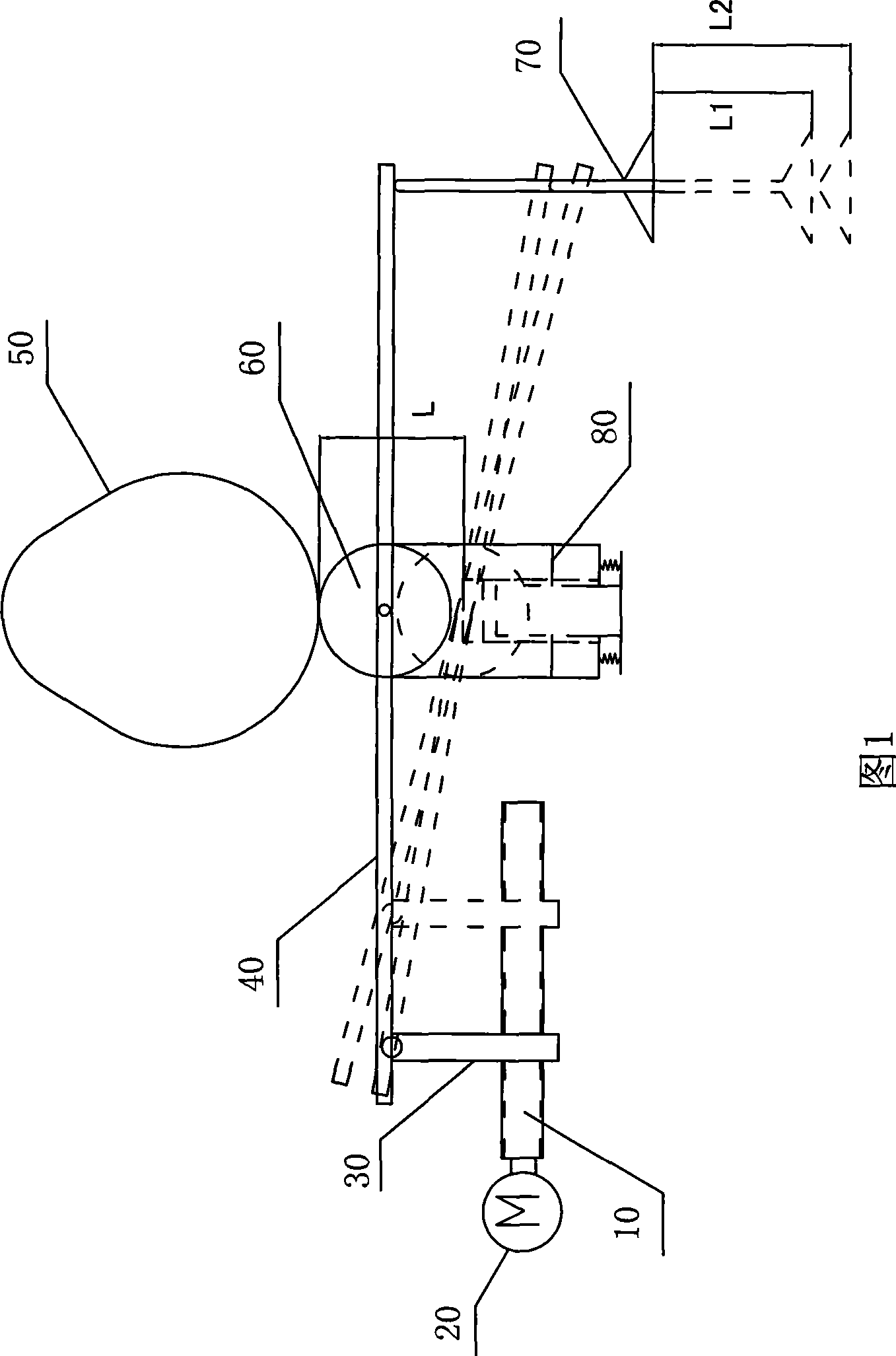
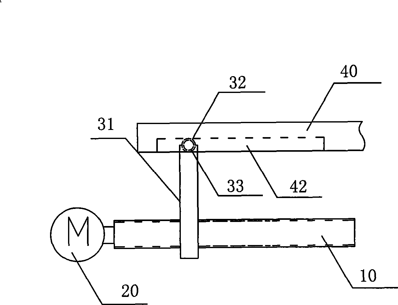
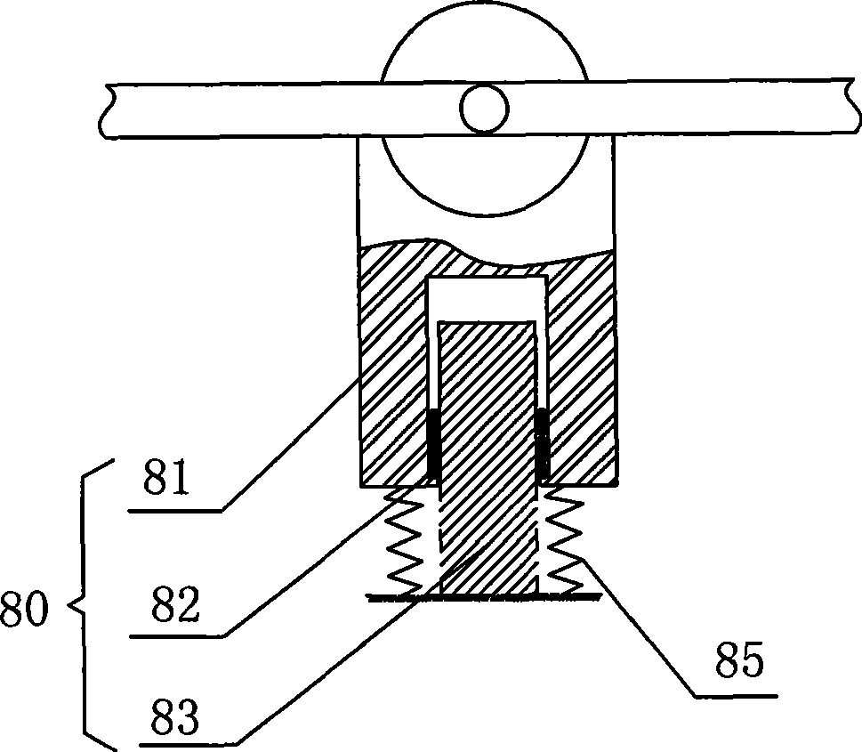
[0015] Please refer to Figure 1 together, figure 2 and image 3 As shown, the continuously variable valve lift device provided by the present invention includes a threaded rod 10, a motor 20 for driving the threaded rod 10 to rotate, a tappet 30 threaded with the threaded rod 10, and a rocker for the tappet 30 to move. The arm shaft 40, the cam 50 located above the rocker shaft 40, the rocker roller 60 interacting with the cam 50, the valve 70 driven by the rocker shaft 40, and the telescopic arm 80 connected with the rocker roller 60 .

[0016] The threaded rod 10 rotates under the drive of the motor 20, thereby driving the tappet 30 connected with the reverse thread to move laterally; wherein the connection mode between the rocker arm roller 60 and the rocker arm shaft 40 is hinged, and the rocker arm roller 60 can rotate around The center is free to rotate; the tappet 30 is slidingly connected with the chute 42 of the rocker shaft 40, and by changing the lateral position ...


PUM


Abstract

The invention relates to a constant variable valve lift device. The device comprises a threaded rod, a motor driving the threaded rod to do rotational movement, a tappet connected with the threaded rod by threads, a rocker shaft movably connected with the tappet, a cam arranged above the rocker shaft, a rocker roller which interacts with the cam and is hinged with the rocker shaft, a valve driven by the rocker shaft and a telescopic arm connected with the rocker roller, wherein the rocker shaft is provided with a slideway which is movably connected with the top of the tappet, and the tappet moves in the slideway. The constant variable valve lift device solves the problem of inconstant variation of the valve lift by making a lever ratio change with the position of a fulcrum of the rocker shaft according to the lever principle.

Description

technical field [0001] The invention relates to a valve lift device of an automobile engine, more specifically, to a continuously variable valve lift device. Background technique [0002] The opening and closing time and lift of the intake and exhaust valves of traditional engines are fixed, so that the engine can only be in the best gas distribution state under a certain working condition, and the engine speed is very low or very high. , its air distribution will be in an unsatisfactory state. For example: when the engine rotates at a low speed, because the valve overlap angle and lift are larger than the ideal value, the flow inertia of the gas is small, and the excessive valve lift is not conducive to the formation of the intake vortex, which makes the fuel and air mix unevenly. Part of the fresh air is taken away by the exhaust gas, which is not conducive to combustion; at high speeds, because the valve lift is smaller than the ideal value, the intake air volume is insu...

Claims


Application Information

Patent Timeline
IPC IPC(8): F01L13/00F02D13/02
CPCY02T10/18Y02T10/12
Inventor 张华熊志江赵辉
Owner CHERY AUTOMOBILE CO LTD
Why Eureka
Try Eureka