Variable valve mechanism

A valve mechanism and variable technology, applied in the direction of mechanical equipment, engine components, machines/engines, etc., can solve problems such as poor intake oil and gas mixing, poor engine economy and emissions, and large intake negative power, etc., to achieve improvement Intake and exhaust conditions, low manufacturing difficulty, and the effect of reducing emissions

Pending Publication Date: 2019-12-31
JILIN UNIV
View PDF0 Cites 0 Cited by
  • Summary
  • Abstract
  • Description
  • Claims
  • Application Information

AI Technical Summary

Problems solved by technology

The valve lift and opening and closing time of the traditional engine remain unchanged, which makes the engine have poor intake air in some working conditions, resulting in poor oil-air mixing, or large intake negative power, and poor engine economy and emissions

Method used


Image

  • Variable valve mechanism
  • Variable valve mechanism
  • Variable valve mechanism

Examples


Embodiment Construction

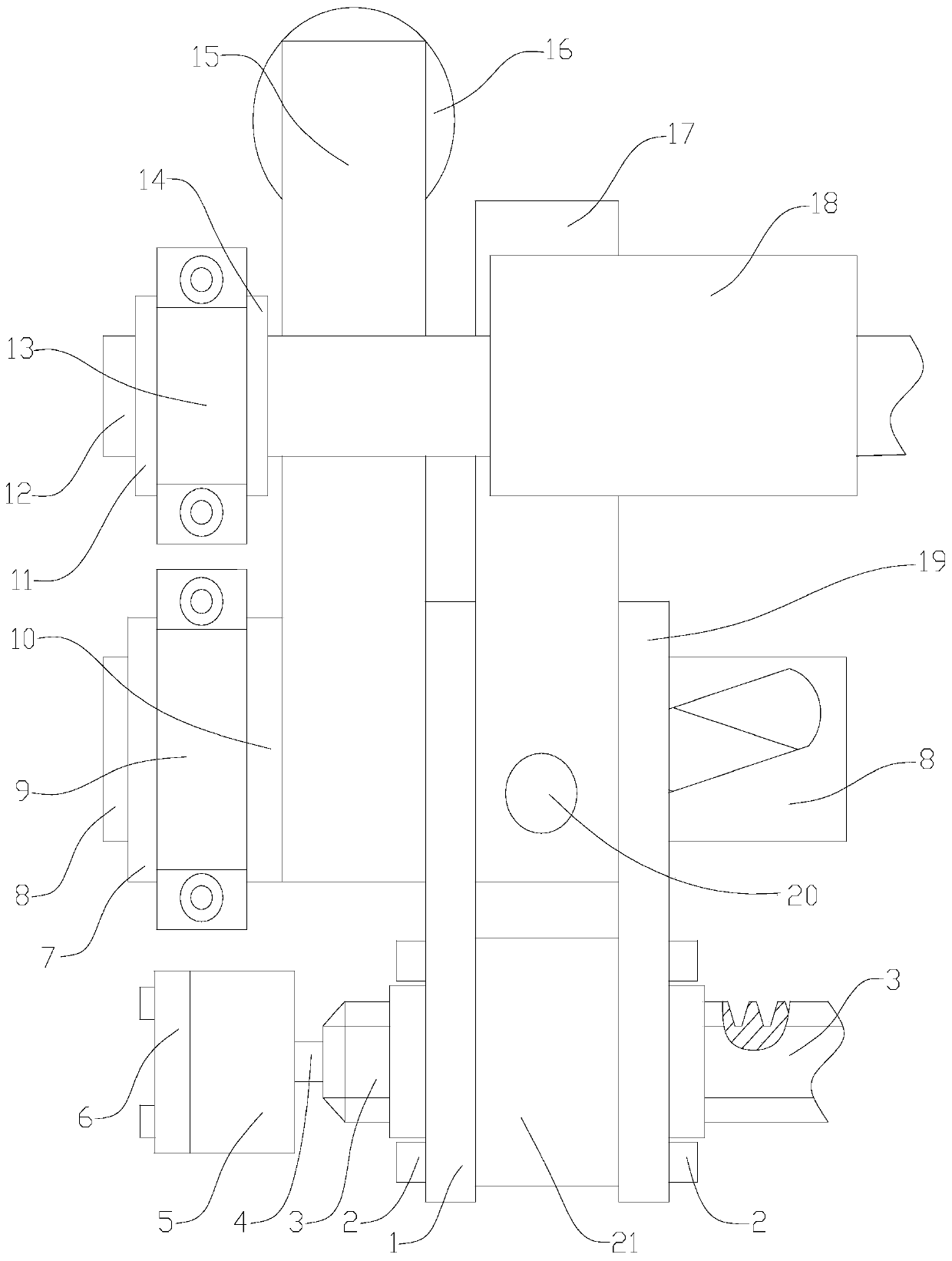
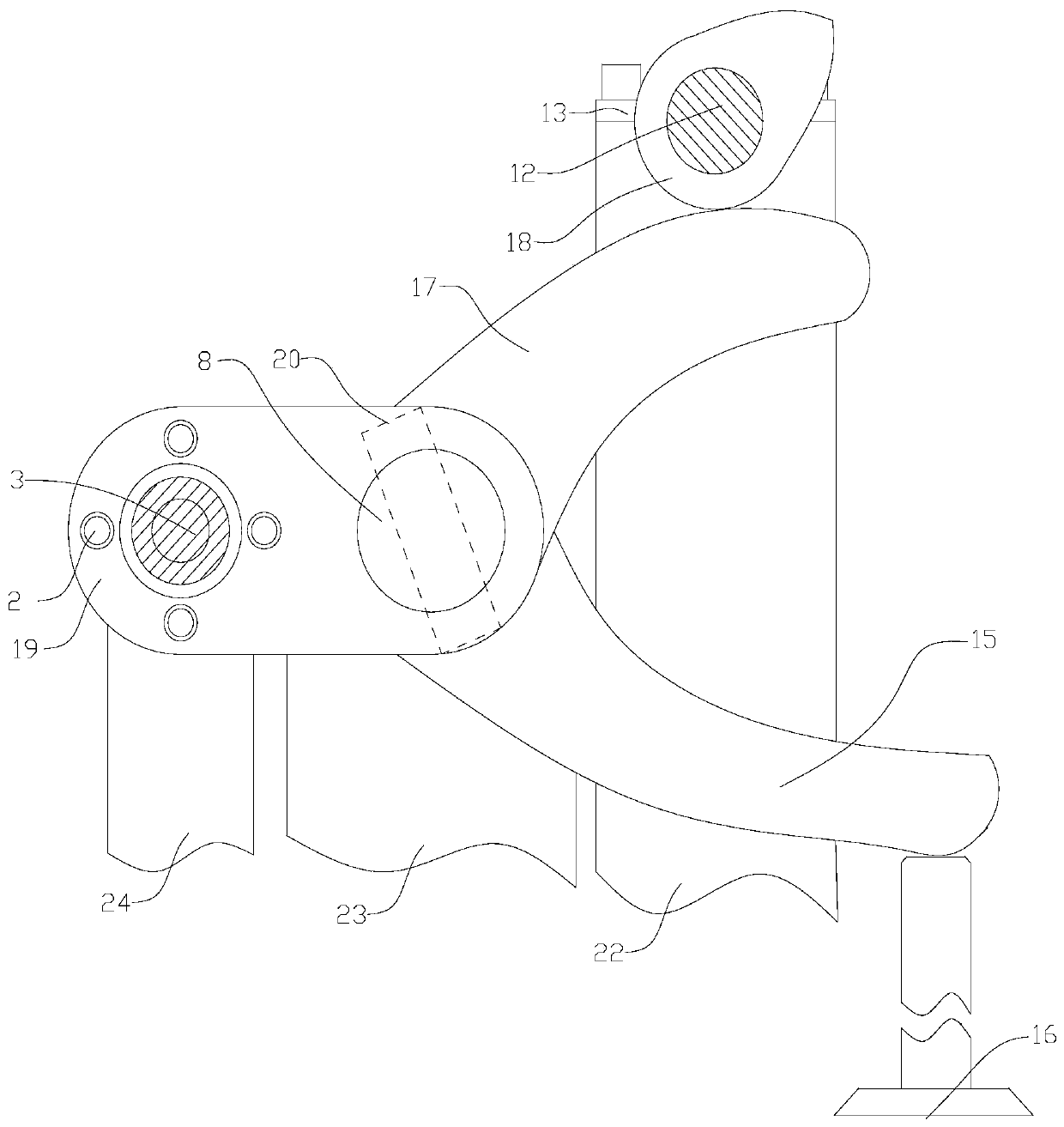
[0022] Referring to the accompanying drawings, the embodiments of the present invention are described, in conjunction with the attached Figure 1-11 Embodiments of the present invention are described in detail.

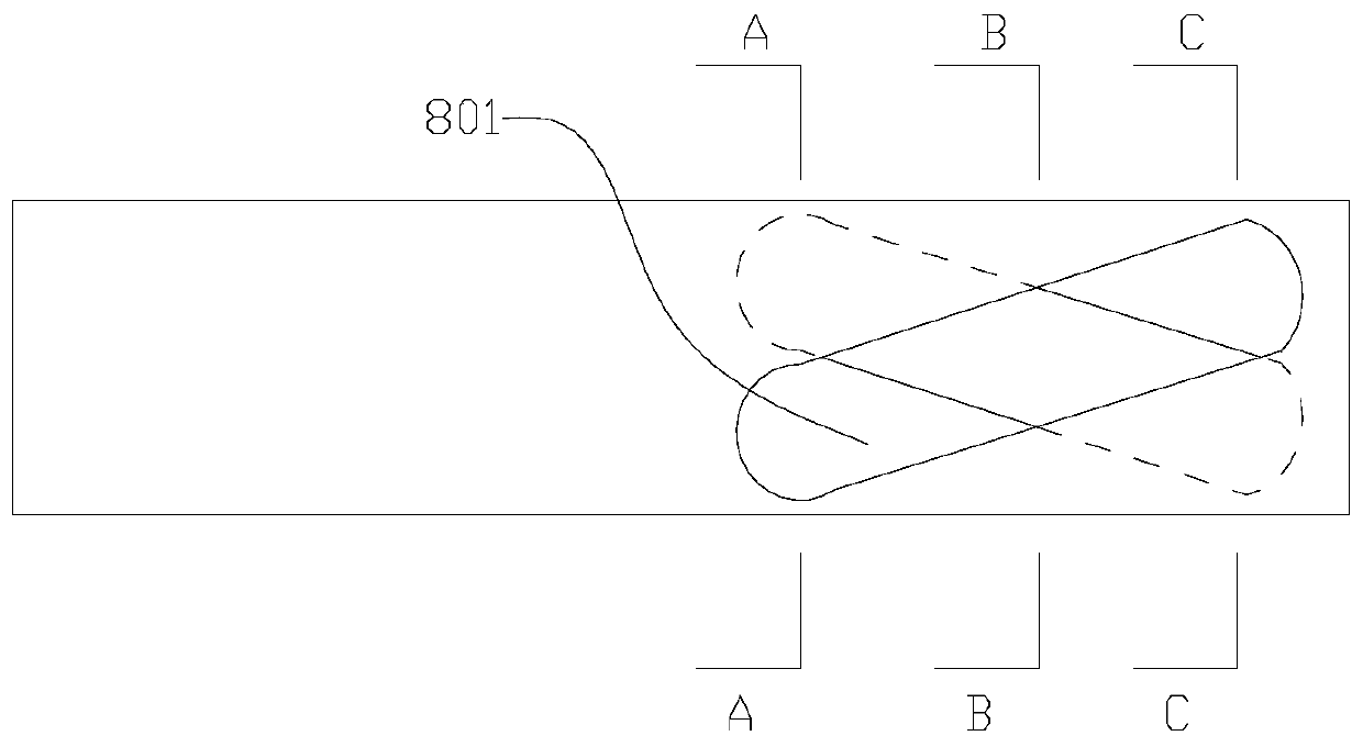
[0023] The main parts that the present invention comprises are: camshaft (12), rocking arm a (15) and rocking arm b (17), rocking arm shaft (8) and valve (16), pin (20) and chute (801) , displacement sleeve (21), motor (5) and related motor shaft (4) and threaded rod (3). The motor shaft drives the threaded rod to move axially through the motor control, and then drives the displacement sleeve to move on the rocker arm, changing the swing law of the rocker arm b (17), and then changing the lift of the valve.

[0024] The camshaft (12) of the present invention is placed between the cover plate b (13) and the support b (22), and is fitted with clearance; the cover plate b (13) and the support b (22) are placed on the limit boss Between c (22) and the limit boss d (14),...


PUM


Abstract

The invention provides a variable valve mechanism comprising main components as follows: a cam shaft (12), a rocker arm (15), a rocker arm b (17), a rocker arm shaft (8), a valve (16), a pin (20), a chute (801), a displacement sleeve (21), a motor (5) and a related motor shaft (4) and threaded rod (3). The motor controls the motor shaft to drive the threaded rod to move axially, then the displacement sleeve is driven to move on the rocker arm, the swinging law of the rocker arm b (17) is changed, and the lift of the valve is changed accordingly.

Description

technical field [0001] The present invention relates to a variable valve mechanism. More specifically, the present invention uses a motor to control a threaded rod to drive a movement of a displacement sleeve on a rocker arm to change the position of the "fulcrum" and the length of the "lever" between the two rocker arms to realize valve control. A mechanism with continuously variable lift. [0002] technical background [0003] With the development of engine technology, the flexible and controllable parameters of the engine are becoming more and more important. The flexible and controllable components of the engine provide a technical basis for the intelligentization of the engine. At the same time, the valve of the engine can be changed into an engine combustion mode and the optimization of gas distribution provides greater potential. The valve lift and opening and closing time of the traditional engine remain unchanged, which makes the engine have poor intake air in some ...

Claims


Application Information

Patent Timeline
Patent Type & Authority Applications(China)
IPC IPC(8): F01L13/00F01L1/18F01L9/04F01L9/22
CPCF01L13/0021F01L1/18F01L2001/186F01L9/20
Inventor 李小平蒋佳辰解方喜苏岩莫嘉乐姜勃
Owner JILIN UNIV
Why Eureka
Try Eureka