Variable valve lift system, engine and automobile

A variable valve lift technology, applied in the direction of engine components, machines/engines, mechanical equipment, etc., can solve the problems of complex structure, limit the maximum output power of the engine, occupancy, etc., and achieve the effect of continuously variable lift

Active Publication Date: 2019-09-10
SAIC MOTOR
View PDF3 Cites 0 Cited by
  • Summary
  • Abstract
  • Description
  • Claims
  • Application Information

AI Technical Summary

Problems solved by technology

[0006] BMW's Valtronic and Nissan's VVEL use switchable intermediate transmission mechanisms to achieve continuous variable valve lift. The advantage of these two systems is that they can achieve continuous variable valve lift. The disadvantage is that the switchable intermediate transmission mechanism requires a set of The control and transmission device is used to drive its work, the structure is complicated, and the control and transmission device is located outside the cylinder, which takes up a large space, squeezes the space for accommodating the cylinder, and limits the selection range of the cylinder, thereby limiting Engine maximum output power
[0007] It can be seen that in the existing variable valve lift technology, the valve lift system with a relatively simple structure can only realize stepwise variable valve lift, while the valve lift system that can realize continuously variable valve lift has a complex structure. , and requires a larger engine space

Method used


Image

  • Variable valve lift system, engine and automobile
  • Variable valve lift system, engine and automobile
  • Variable valve lift system, engine and automobile

Examples


Embodiment Construction

[0036] In order to make the above objects, features and advantages of the present invention more comprehensible, specific embodiments of the present invention will be described in detail below in conjunction with the accompanying drawings.

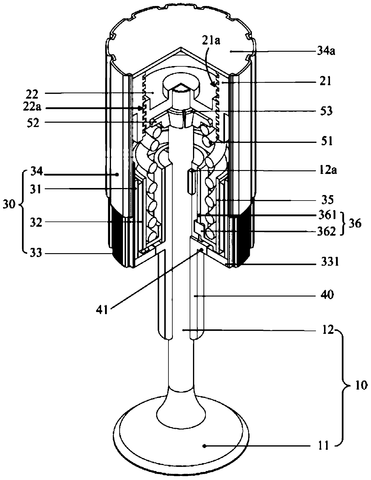
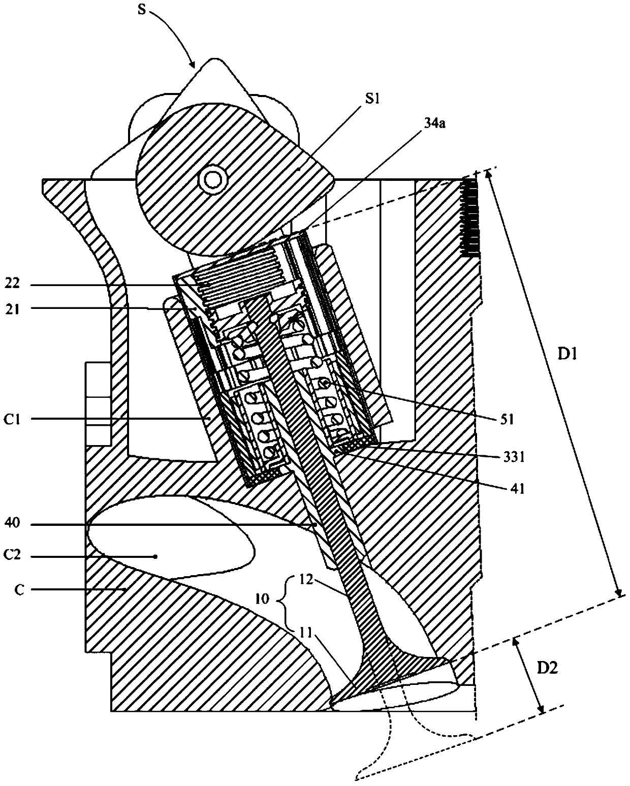
[0037] An embodiment of the present invention provides a variable valve lift system, referring to figure 1 and combine figure 2 It includes a valve 10, a gear component for driving the valve 10 to move in the axial direction, and a driving part 30 for driving the gear component to move.

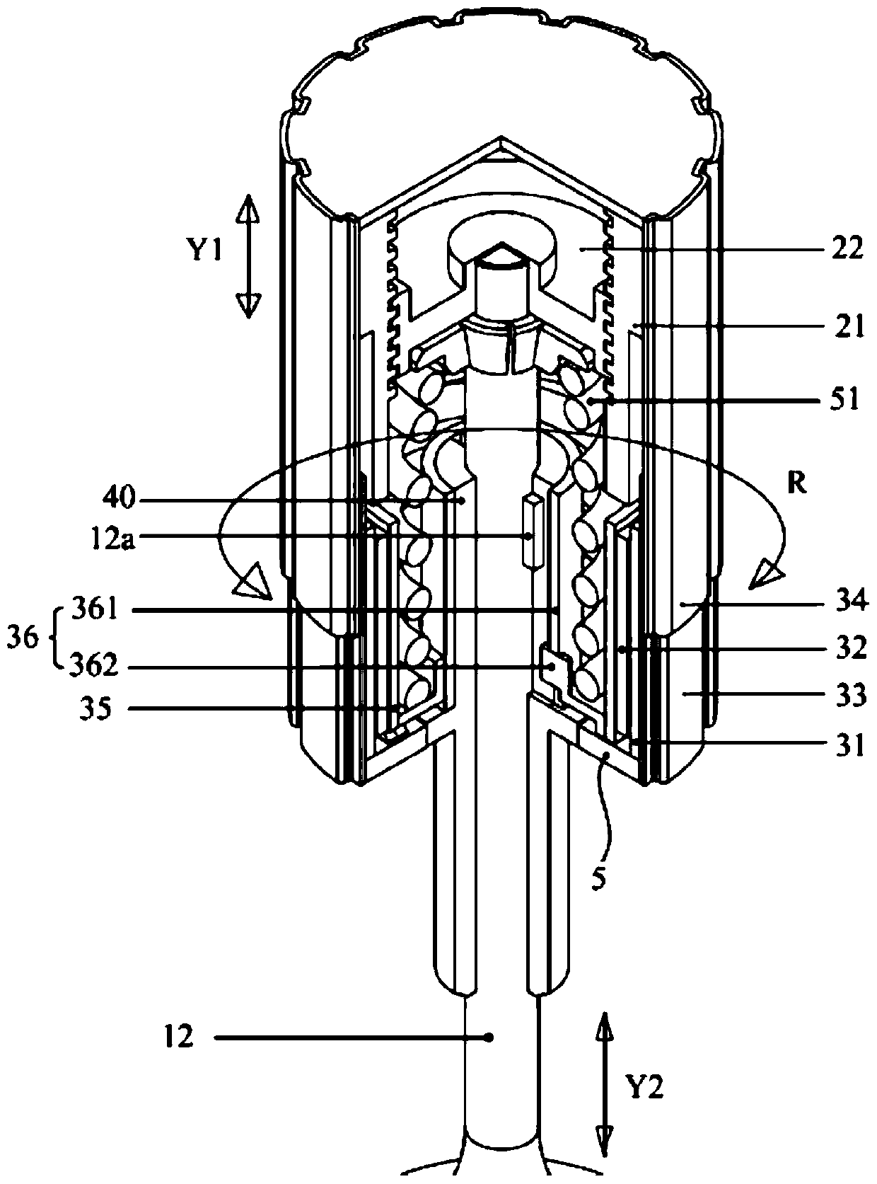
[0038] The valve 10 has a valve head 11 and a valve stem 12 . The gear part includes a first gear 21 and a second gear 22 meshing with each other. The first gear 21 has a cylindrical inner peripheral surface, and a first helical tooth 21a is provided on the inner peripheral surface; the second gear 22 is coaxially sleeved on the Inside the first gear 21 and coaxially connected with the valve stem 12 , the second gear 22 has a cylindrical outer peripher...


PUM


Abstract

The invention relates to a variable valve lift system, an engine and a car. The variable valve lift system comprises a valve, a first gear, a second gear and a driving part; the valve is provided with a valve head and a valve rod; the first gear is provided with a columnar inner circumferential face which is provided first helical teeth; the second gear is sleeved with the first gear, is coaxially connected with the valve rod, and is provided with a columnar outer circumferential face, and the columnar outer circumferential face is provided with second helical teeth meshed with the first helical teeth; and the driving part is used for driving the first gear to rotate, the second gear is rotated by rotation of the first gear to drive the valve to move in the axial direction. By means of the system, transmission of the first gear is converted into rectilinear motion of the second gear through the meshed helical teeth, then the valve is driven by the second gear to move in the axial direction, and therefore the lift of the valve is continuously changed to adjust the valve opening degree, and the continuously variable valve lift is achieved.

Description

technical field [0001] The invention relates to the field of automobiles, in particular to a variable valve lift system, an engine and an automobile. Background technique [0002] The valve of the engine can be compared to a door. The angle and time of the door opening determine the air flow in and out. The larger the opening angle of the door and the longer the opening time, the greater the air flow in and out, otherwise the smaller the air flow in and out. Thus, the concepts of valve lift and valve timing are born, wherein the valve lift is like the angle at which the door is opened (referred to as the valve opening), and the valve timing is like the time at which the door is opened. [0003] Among them, for the valve lift, when the car is running at a low speed, the engine power required is small, so the intake and exhaust volume requirements are small, and a relatively small valve lift is required; when the car is running at a high speed, the required engine power The ...

Claims


Application Information

Patent Timeline
Patent Type & Authority Patents(China)
IPC IPC(8): F01L13/00
Inventor 张家宁张钊罗辑李俊鹏梅爱群
Owner SAIC MOTOR
Why Eureka
Try Eureka