A mechanical adjustment device of a hydraulically driven fully variable valve

A mechanical adjustment and driving technology, applied in valve devices, mechanical equipment, engine components, etc., can solve the problems of high price, high energy consumption of solenoid valves, and unsatisfactory reliability, so as to reduce pumping loss and realize load Control and improve the effect of aeration efficiency

Active Publication Date: 2017-12-01
JILIN UNIV
View PDF8 Cites 0 Cited by
  • Summary
  • Abstract
  • Description
  • Claims
  • Application Information

AI Technical Summary

Problems solved by technology

[0004] The purpose of the present invention is to overcome the disadvantages of high energy consumption and high-speed response, durability, and reliability of the existing hydraulically driven variable valve mechanism solenoid valve, which cannot meet the needs and are expensive, and provide a simple and reliable structure that can flexibly control the valve. Hydraulic fully variable valve mechanical adjustment device for lift and valve timing

Method used


Image

  • A mechanical adjustment device of a hydraulically driven fully variable valve
  • A mechanical adjustment device of a hydraulically driven fully variable valve
  • A mechanical adjustment device of a hydraulically driven fully variable valve

Examples


Embodiment Construction

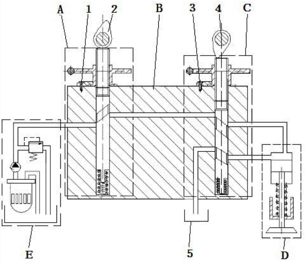
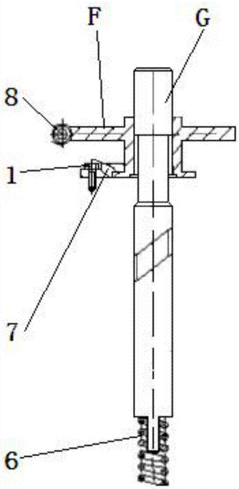
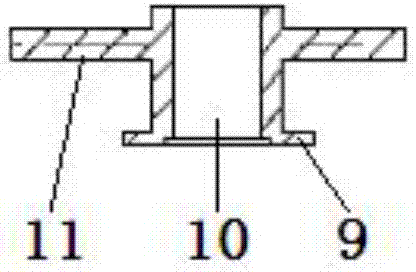
[0033] The present invention is described in detail below in conjunction with accompanying drawing:

[0034] Valve opening and closing adjustment mechanism ⅠA, base B, valve opening and closing adjustment mechanism ⅡC, hydraulic piston valve group D, hydraulic oil supply adjustment mechanism E, worm gear sleeve ⅠF, plunger ⅠG, worm gear sleeve ⅡH, plunger ⅡI, bolt Ⅰ1 , cam Ⅰ2, bolt Ⅱ3, cam Ⅱ4, fuel tank Ⅱ5, spring Ⅰ6, positioning plate Ⅰ7, adjusting worm Ⅰ8, chassis Ⅰ9, center hole Ⅰ10, worm wheel Ⅰ11, boss Ⅰ12, spiral groove Ⅰ13, boss Ⅱ14, protruding rod Ⅰ15, Bolt hole I16, plunger guide rail I17, oil passage II18, bolt hole II19, plunger guide rail II20, oil passage IV21, oil passage V22, oil passage III23, oil passage I24, spring II25, positioning plate II26, adjusting worm II27, chassis Ⅱ28, center hole Ⅱ29, worm wheel Ⅱ30, boss Ⅲ31, spiral groove Ⅱ32, boss Ⅳ33, spiral groove Ⅲ34, convex rod Ⅱ35, oil inlet hole 36, piston sleeve 37, center hole Ⅲ38, valve 39, spring seat 4...


PUM


Abstract

A mechanical adjustment device for a hydraulically driven fully variable valve belongs to the technical field of engines. The two plungers of the two-valve opening and closing adjustment mechanism of the present invention are respectively placed in the two guide rails of the base; the tops of the two plungers respectively contact the two cams; During the air stroke: the spiral groove Ⅰ of the plunger Ⅰ is connected with the oil passage Ⅰ and oil passage Ⅱ of the base; the spiral groove Ⅱ of the plunger Ⅱ is connected with the oil passage Ⅱ and oil passage Ⅳ of the base; during the exhaust stroke: the plunger Ⅱ The spiral groove III of the base is connected with the oil passage III and the oil passage V of the base; the oil inlet hole of the hydraulic piston valve group, the oil drain hole of the hydraulic piston valve group, and the oil pipe II of the hydraulic oil supply adjustment mechanism are respectively connected with the oil passages IV and V of the base. The oil passage V is connected with the oil passage I; the invention can realize continuous variable valve lift and valve phase, can maintain the maximum lift of the valve within a certain period of time, can realize no-throttle load control of gasoline engines, reduce pumping loss, and improve Inflatable efficiency and the realization of Miller cycle, to achieve the effect of energy saving and emission reduction, simple structure, easy to control.

Description

technical field [0001] The invention belongs to the technical field of engines, and in particular relates to a mechanically regulated fully variable valve mechanism of a hydraulically driven internal combustion engine. Background technique [0002] Due to the fixed structure of the traditional engine's valve mechanism, the valve timing cannot be changed during the operation of the engine. Usually, it can only ensure the performance of the internal combustion engine in a certain working condition, and it cannot take into account the requirements of various working conditions at the same time. It is difficult To achieve the real optimal valve timing. These fixed valve operating parameters are just a compromise of various comprehensive contradictions of internal combustion engine operation requirements for valve work under different operating conditions. Therefore, in order to meet the different valve timing requirements under different working conditions, improve the economy ...

Claims


Application Information

Patent Timeline
Patent Type & Authority Patents(China)
IPC IPC(8): F01L9/02F01L13/00F01L1/34F01L9/11
CPCF01L1/34F01L13/00F01L9/12Y02T10/12
Inventor 解方喜洪伟姚卓彤苏岩姜北平李小平杨文海代志尧代春雨王升黄震康尔凝赵玉祥郭淑芳
Owner JILIN UNIV
Why Eureka
Try Eureka