Engine rocker type variable valve device

A rocker arm type, engine technology, applied in the direction of engine components, machines/engines, valve devices, etc., can solve the problems of electro-hydraulic variable valve timing mechanism response lag, fast seating speed, large impact force, etc., to achieve responsiveness Sensitive, lightened mass, responsive effect

Pending Publication Date: 2019-07-16
JILIN UNIV
View PDF0 Cites 0 Cited by
  • Summary
  • Abstract
  • Description
  • Claims
  • Application Information

AI Technical Summary

Problems solved by technology

The electro-hydraulic variable valve timing mechanism has the disadvantages of lagging response, fast seating speed, large impact force and high cost

Method used


Image

  • Engine rocker type variable valve device
  • Engine rocker type variable valve device
  • Engine rocker type variable valve device

Examples


Embodiment Construction

[0030] The present invention is described in detail below in conjunction with accompanying drawing:

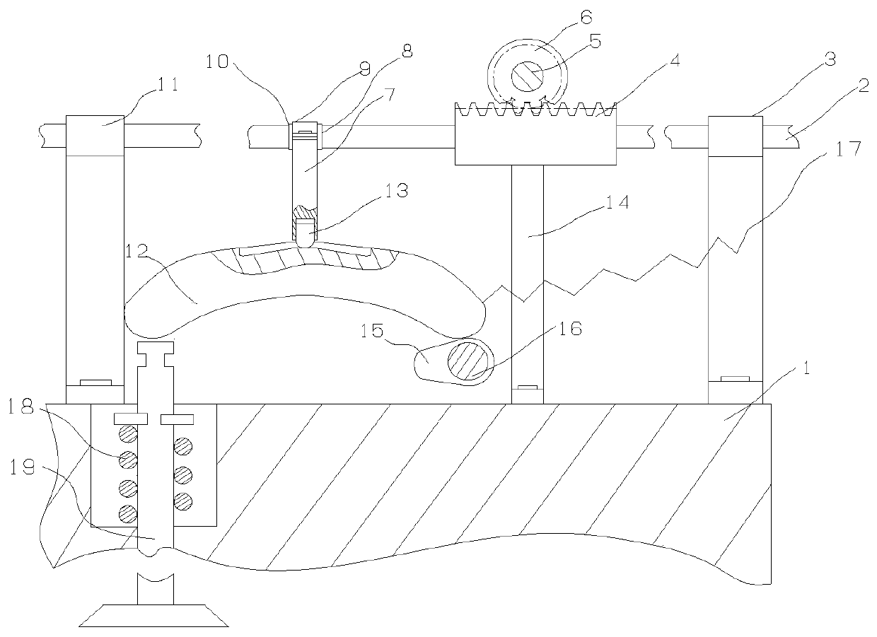
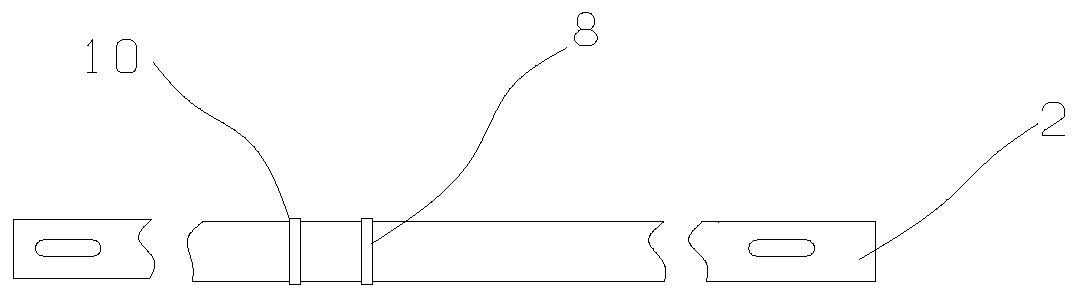
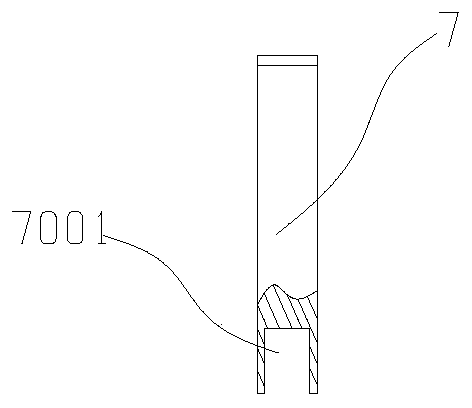
[0031] refer to figure 1 , figure 2 The engine rocker arm type variable valve device of the present invention comprises the following structures: cylinder head 1, rack shaft 2, rack shaft bracket a3, rack 4, gear shaft 5, gear 6, connecting rod 7, limit ring Platform a8, upper cover plate 9, limit ring platform b10, rack shaft support b11, rocking arm 12, slide block 13, motor support 14, cam 15, camshaft 16, thrust spring 17, valve spring 18, valve 19.

[0032] refer to image 3 , Figure 4 , Figure 6 , The engine rocker-type variable valve device of the present invention includes a connecting rod groove 7001 , a rocker groove 1201 , and a rack hole 4001 .

[0033] refer to figure 1 , image 3 , Figure 4 :

[0034] The rack shaft support a3, the rack shaft support b11 and the motor support 14 are all fixed on the cylinder head 1 with two bolts; the motor is fixedl...


PUM


Abstract

The invention discloses an engine rocker type variable valve device. A cam, a motor, a gear rack transmission, a rocker and a connecting rod are included. The engine rocker type variable valve deviceis fixed to an air cylinder cover. When the rotation speed of an engine changes, the motor is used for driving a gear 6 to rotate with the corresponding angle, a rack 4, a rack shaft 2, the connectingrod 7 and a sliding block 13 are driven to do the same-ration horizontal movement motion, and accordingly the rocker ratio of the rocker 12 is changed; through pushing of the cam 15, the lift of a valve 19 is continuous and changeable, and the problem that under different work conditions, the valve lift of the engine cannot be continuous or changeable is solved; and the engine conducts sufficientair inflow and outflow under different work conditions, the combustion environment in a cylinder is changed, and accordingly, fuel economy and emission performance of the engine are improved.

Description

technical field [0001] The invention relates to an automobile engine component or equipment, in particular to an engine rocker-type variable valve device. Background technique [0002] With the increasingly stringent national standards for energy saving and emission reduction, engine miniaturization has become one of the feasible technologies to meet the requirements. The core of engine miniaturization technology is exhaust gas turbocharging system, gasoline engine direct injection and variable valve timing. Among them, the main function of the variable valve timing of the engine is to control the opening and closing time, duration and lift of the valve according to the working cycle of each cylinder, so as to improve the combustion process, reduce the emission of harmful pollutants, and improve engine performance. . [0003] At present, the engine mainly adopts the variable timing technology based on the cam structure and the variable valve timing technology without cam. ...

Claims


Application Information

Patent Timeline
Patent Type & Authority Applications(China)
IPC IPC(8): F01L13/00F01L1/18
CPCF01L1/183F01L13/0021F01L2013/10F01L2013/103
Inventor 解方喜李晓娜洪伟刘洪涛杨野周思佟孙博赵志宏王斌石卜从蓝大舜马兆壮
Owner JILIN UNIV
Why Eureka
Try Eureka