Shifting transmission device
A technology of variable speed transmission and variable speed section, which is applied to transmission devices, gear transmission devices, fluid transmission devices, etc., can solve problems such as unstable speed change action, and achieve the effect of high speed change performance and output performance, and it is not easy to change speed.
- Summary
- Abstract
- Description
- Claims
- Application Information
AI Technical Summary
Problems solved by technology
Method used
Image
Examples
Embodiment 1
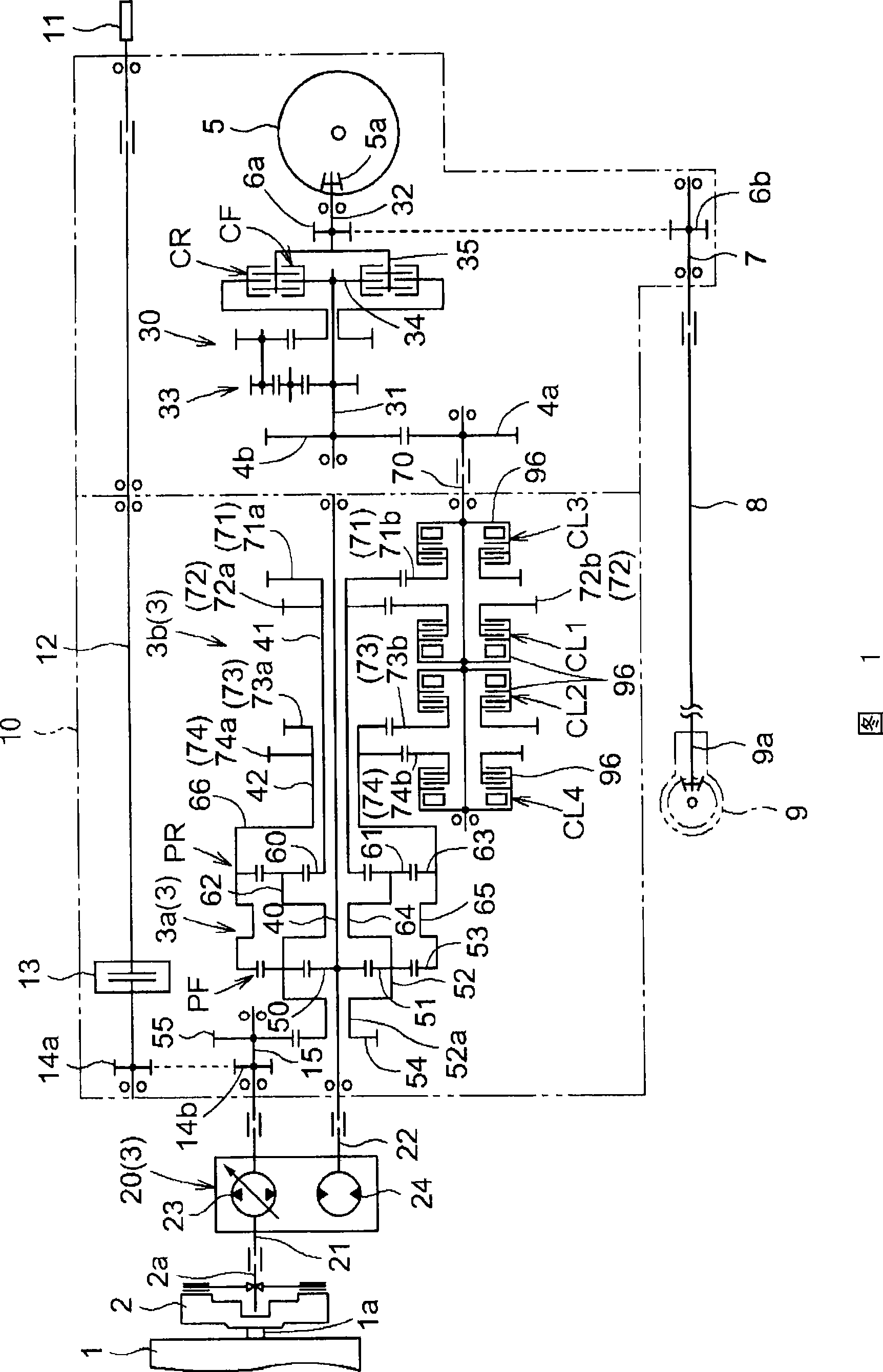
[0070] FIG. 1 is a line diagram of a variable speed transmission 3 according to Embodiment 1. As shown in FIG. The speed change transmission device 3 of the first embodiment is mounted on a travel transmission device provided in a work vehicle such as a tractor.
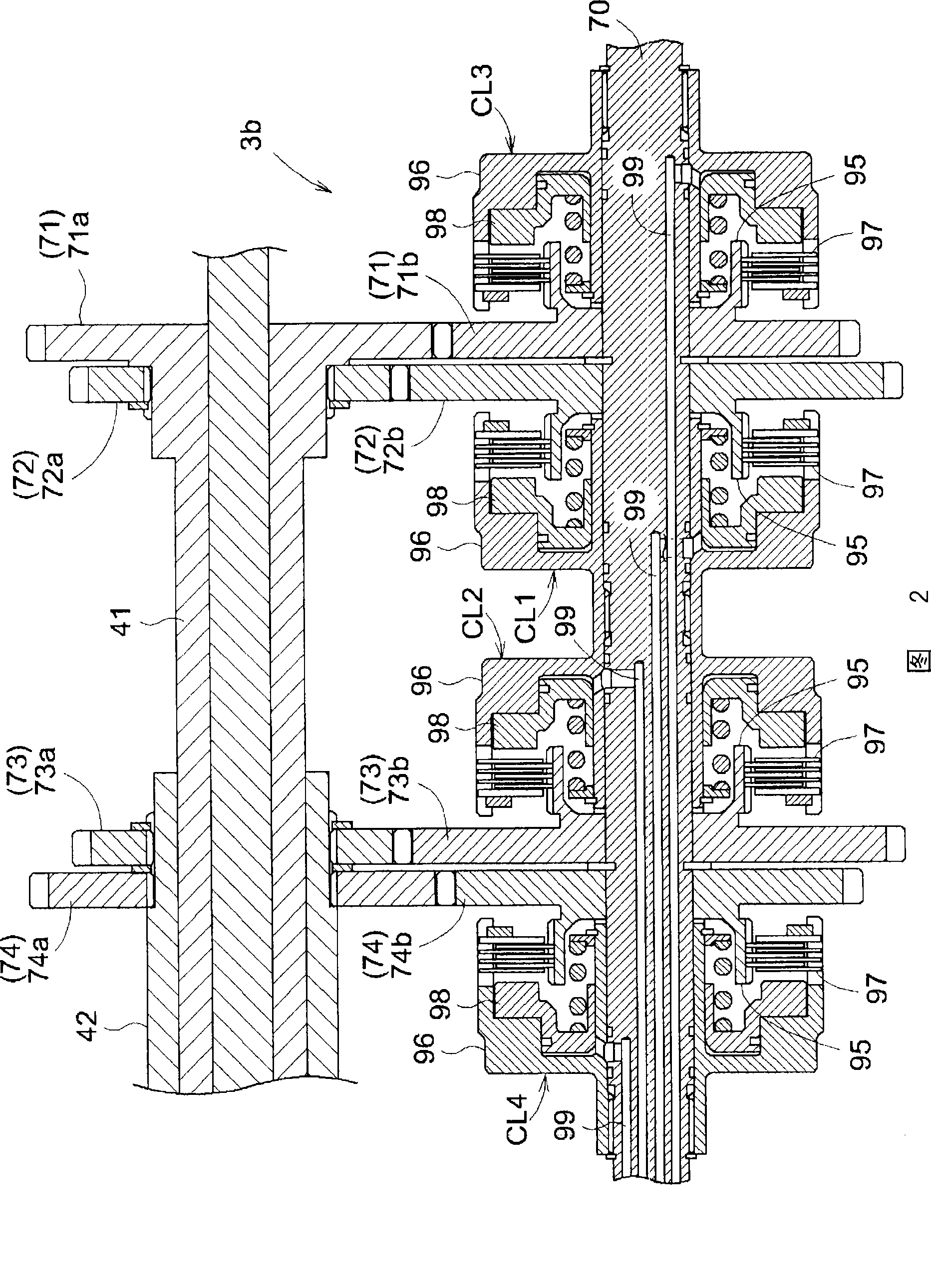
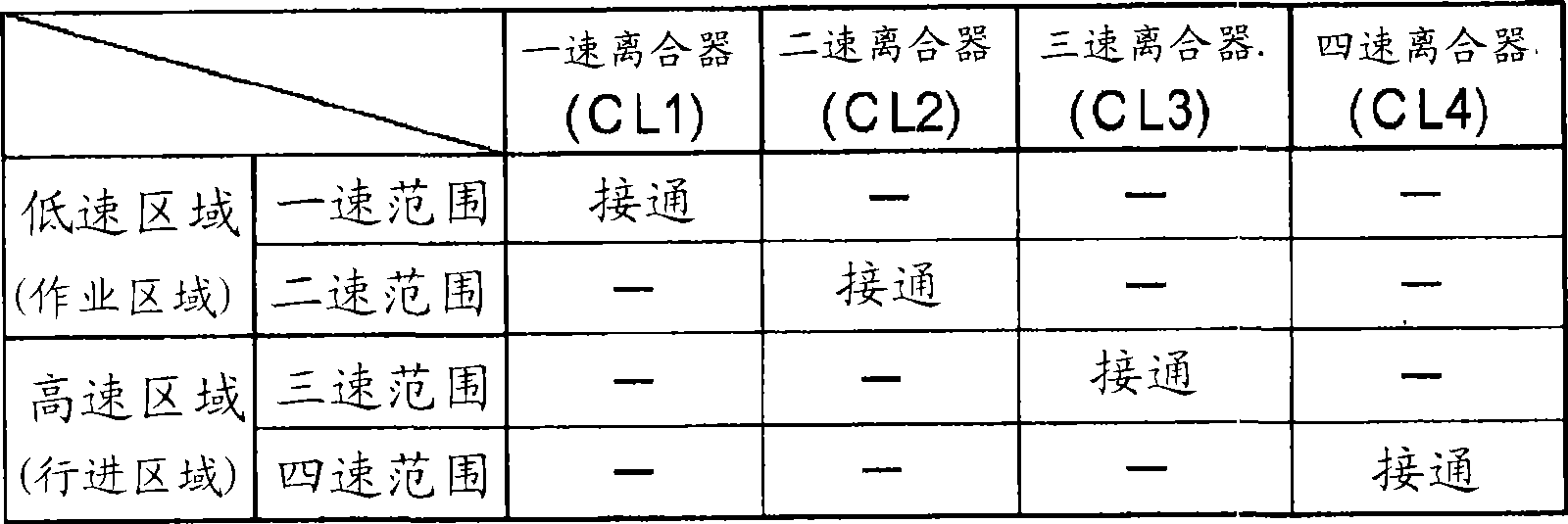
[0071] The traveling transmission includes the main clutch 2 into which the output from the output shaft 1a of the engine 1 is input, the input shaft 21 and the above-mentioned speed change transmission 3 linked with the output shaft 2a of the main clutch 2, the input shaft 31 and the transmission gear 4a, 4b and The forward and reverse switching device 30 linked by the output shaft 70 of the speed change transmission device 3, the rear wheel differential mechanism 5 linked by the input gear 5a and the output shaft 32 of the forward and reverse switching device 30, and the above-mentioned forward and reverse via transmission gears 6a and 6b. The output shaft 7 for front wheels interlocked with the output shaft 32 of ...
Embodiment 2
[0104] FIG. 6 is a line diagram of the speed change transmission device 103 of the second embodiment. Here, the same reference numerals are used for the same components as those in Embodiment 1, and the description will not be repeated basically. The speed change transmission device 103 of the second embodiment is equipped on a travel transmission device provided in a tractor. This travel transmission includes a main clutch 2 into which the output from the output shaft 1 a of the engine 1 is input, the above-mentioned speed change transmission 103 into which the output from the main clutch 2 is input, and a forward drive coupled with the output shaft 170 of the speed change transmission 103 . The reverse switching device 30 , the rear wheel differential mechanism 5 interlocked with the output shaft 32 of the forward and reverse switching device 30 , and the front wheel differential mechanism 9 interlocked with the output shaft 32 of the forward and reverse switching device 30 ...
Embodiment 3
[0130] FIG. 10 is a line diagram of the speed change transmission 3 of the third embodiment. This traveling transmission includes a main clutch 2 into which the output from the output shaft 1a of the engine 1 is input, the above-mentioned speed change transmission 3 into which the output from the main clutch 2 is input, and an output rotating body which is the output of the speed change transmission 3 . The forward-backward switching device 30 linked with the shaft 70, the rear wheel differential mechanism 5 linked with the output shaft 32 of the forward-backward switching device 30, and the front wheel differential mechanism 9 linked with the output shaft 32 of the forward-backward switching device 30 .
[0131] Comparing the traveling transmission equipped with the speed change transmission 3 of Example 3 with the traveling transmission equipped with the speed change transmission 3 of Example 2, it is found that the main clutch 2, the forward / reverse switching device 30, and...
PUM
 Abstract
Description
Claims
Application Information
 - R&D
- Intellectual Property
- Life Sciences
- Materials
- Tech Scout
- Unparalleled Data Quality
- Higher Quality Content
- 60% Fewer Hallucinations
Browse by: Latest US Patents, China's latest patents, Technical Efficacy Thesaurus, Application Domain, Technology Topic, Popular Technical Reports.
© 2025 PatSnap. All rights reserved.Legal|Privacy policy|Modern Slavery Act Transparency Statement|Sitemap|About US| Contact US: help@patsnap.com


