
Multiple input multiple output signal receiving apparatus with optimized performance

A signal receiving device, multi-output technology, applied in transmission systems, electrical components, etc., can solve the problems of large equipment size, high manufacturing cost, high energy consumption rate, etc.

Inactive Publication Date: 2009-05-13
CISCO TECH INC
View PDF0 Cites 11 Cited by
  • Summary
  • Abstract
  • Description
  • Claims
  • Application Information

AI Technical Summary

Problems solved by technology

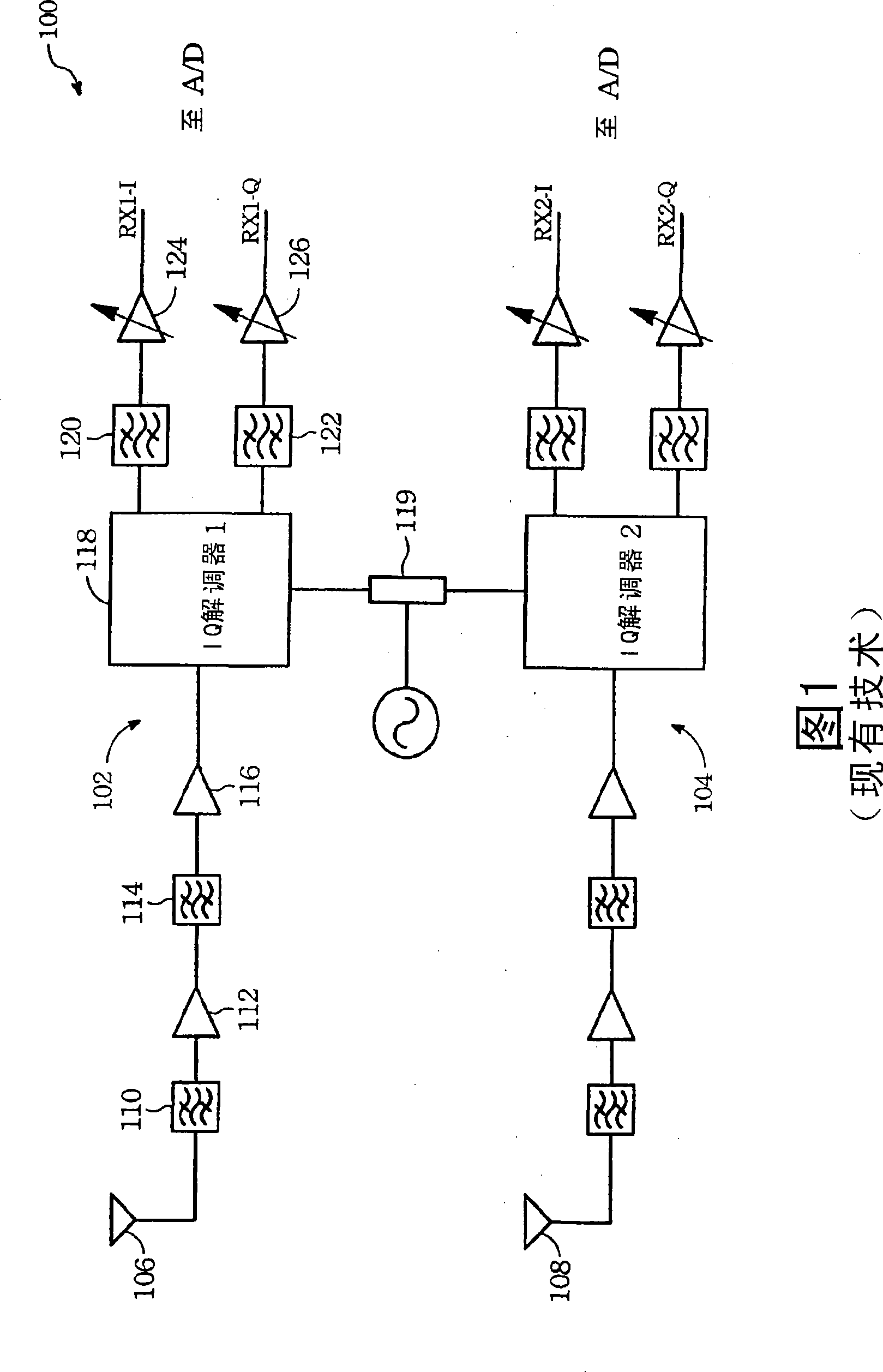
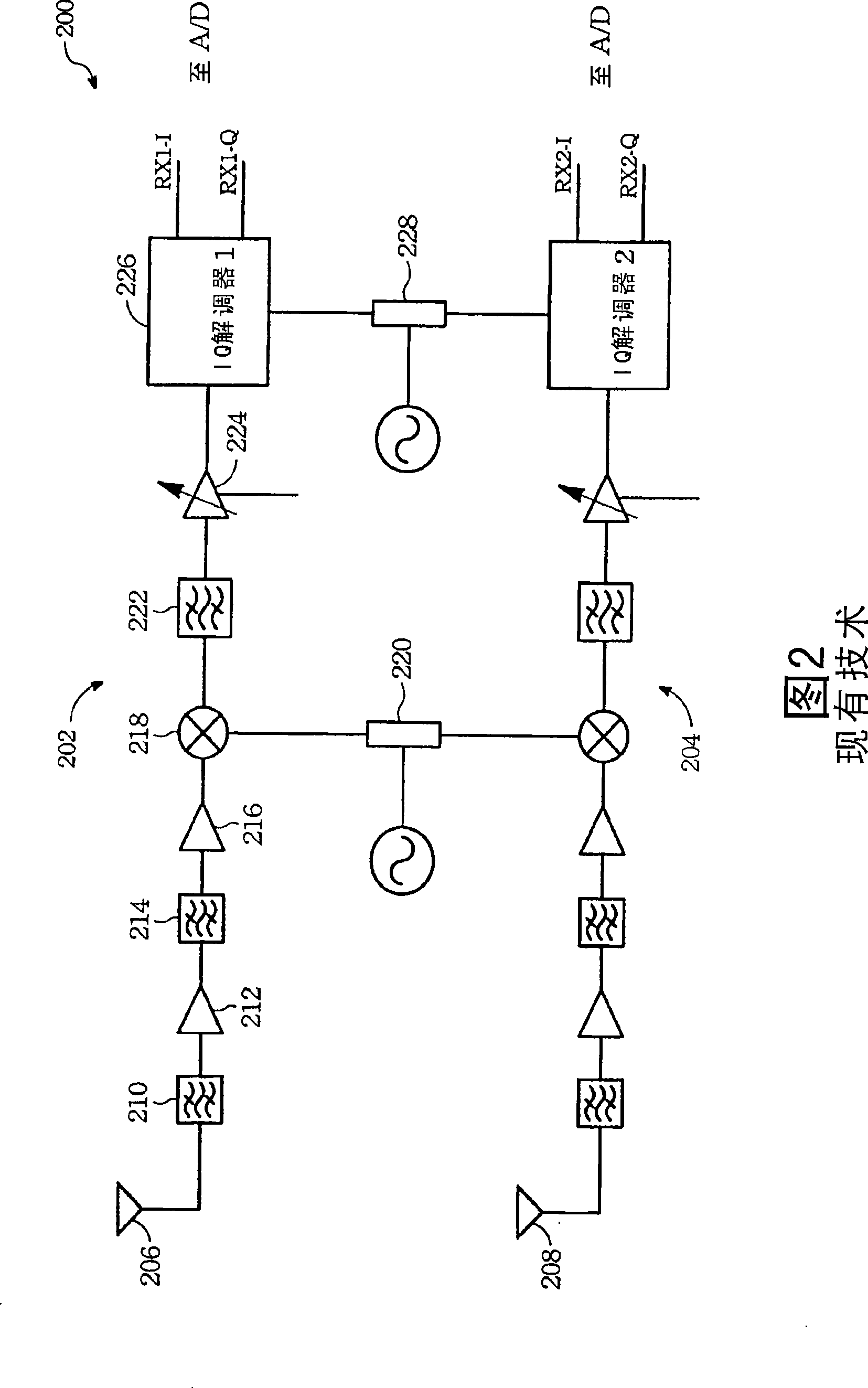
However, since the superheterodyne MIMO signal receiving apparatus 200 requires an additional device to down-convert the RF signal received from the antenna into an IF signal, it has disadvantages such as high manufacturing cost, high power consumption rate, and large device size.

Method used


Image

  • Multiple input multiple output signal receiving apparatus with optimized performance
  • Multiple input multiple output signal receiving apparatus with optimized performance
  • Multiple input multiple output signal receiving apparatus with optimized performance

Examples


Embodiment Construction

[0021] The present invention describes a MIMO signal receiving device with optimized performance. Various embodiments of the invention are described below for the purpose of explaining the principles thereof only. It should be understood that those skilled in the telecommunications arts can devise various equivalents embodying the principles of the invention, although not explicitly described herein.

[0022] FIG. 4 illustrates a proposed MIMO signal receiving device according to one embodiment of the present invention. The apparatus 400 includes a first antenna 402 and a second antenna 404 coupled to an antenna switching module 406 which is further coupled to a superheterodyne receiver 408 and a direct conversion receiver 410 . Antenna switching module 406 selectively directs the first RF signal received from first antenna 402 and the second RF signal received from second antenna 404 to superheterodyne receiver 408 and / or direct conversion receiver 410 . The analog outputs ...


PUM


Abstract

A MIMO signal receiving apparatus includes a first antenna (402 in chart 4) for receiving a first RF signal; a second antenna (404) for receiving a second RF signal; a superheterodyne receiver for receiving one or all of the first and second RF signals into at least one first analog signal; a direct conversion receiver (410) for converting one or all of the first and second RF signals into at least one second signal; and an antenna switching module coupling the first and second antennas to the superheterodyne receiver (408) and the direct conversion receiver for electively directing the first and second RF signals to the superheterodyne receiver and / or the direct conversion receiver, depending on an antenna switch control signal indicating a signal quality derived from the first and second analog signals.

Description

[0001] cross reference [0002] This application claims the title "Multiple Receiver Architecture Optimized for Performance, Cost, and Size for Use in MIMO Mobile Wireless Broadband Receivers," filed June 27, 2006. and Size for use in MIMO Mobile Wireless Broadband Receiver."), the priority of U.S. Patent Provisional Application No. 60 / 816,929. technical field [0003] The present invention relates generally to wireless communications, and more particularly to multiple-input multiple-output (MIMO) signal receiving devices with optimized performance. Background technique [0004] MIMO technology has received a lot of attention in the telecommunications field because it allows a significant increase in throughput with the same bandwidth and overall power consumption. MIMO technology exploits phenomena such as multipath propagation to increase data throughput and range, or to reduce bit error rates. In general, MIMO techniques increase the spectral efficiency of wireless tel...

Claims


Application Information

Patent Timeline
IPC IPC(8): H04B1/06
Inventor 安·图耶·巴纳苏勇徐新光
Owner CISCO TECH INC
Learn More