Multi-spindle machining center

A machining center and multi-spindle technology, applied in metal processing, metal processing equipment, metal processing machinery parts, etc., can solve problems such as large overall space

Inactive Publication Date: 2009-05-20
ALFING KESSLER SONDERMASCH
View PDF1 Cites 3 Cited by
  • Summary
  • Abstract
  • Description
  • Claims
  • Application Information

AI Technical Summary

Problems solved by technology

However, a relatively large overall space is requ

Method used


Image

  • Multi-spindle machining center
  • Multi-spindle machining center
  • Multi-spindle machining center

Examples


Embodiment Construction

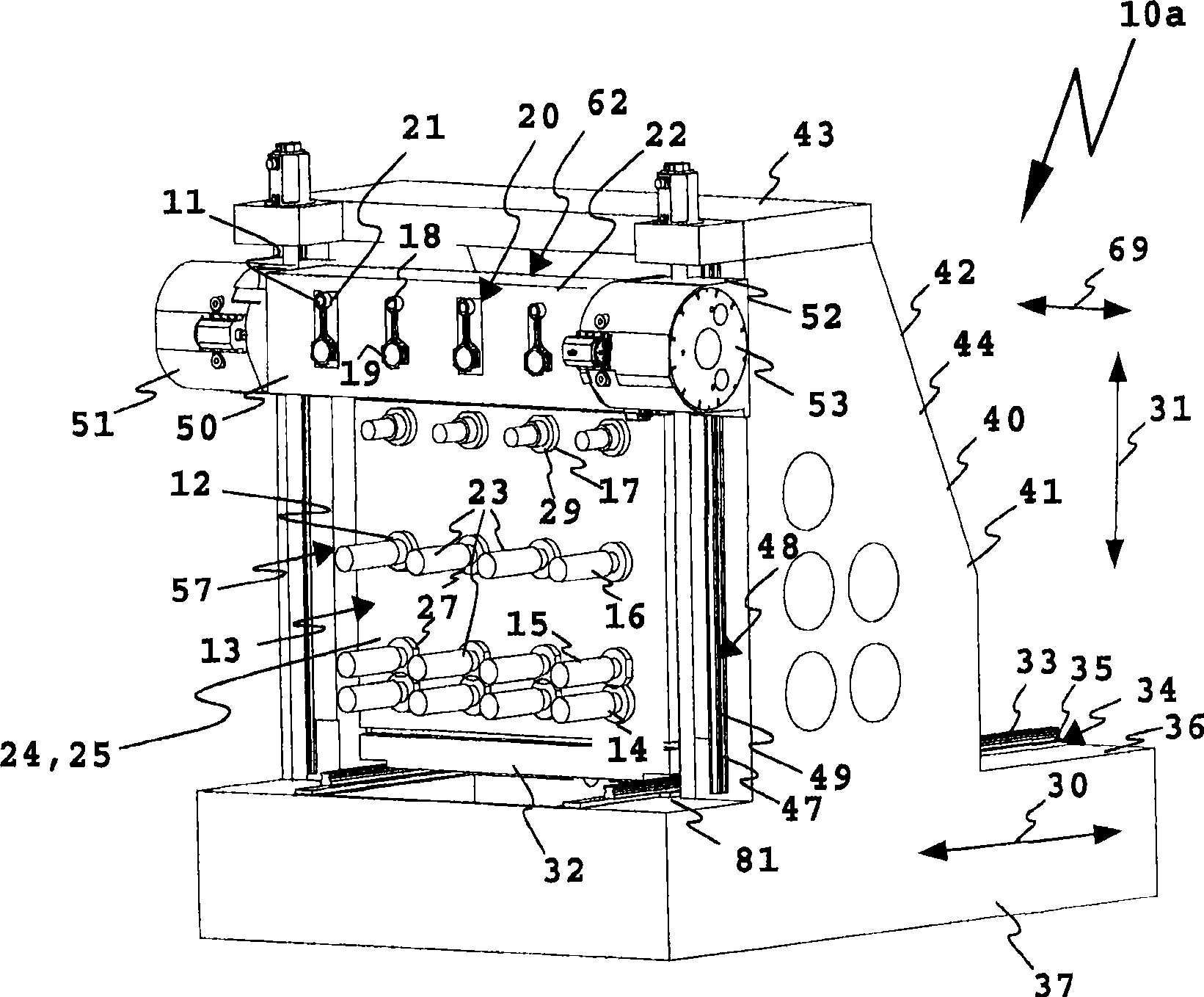
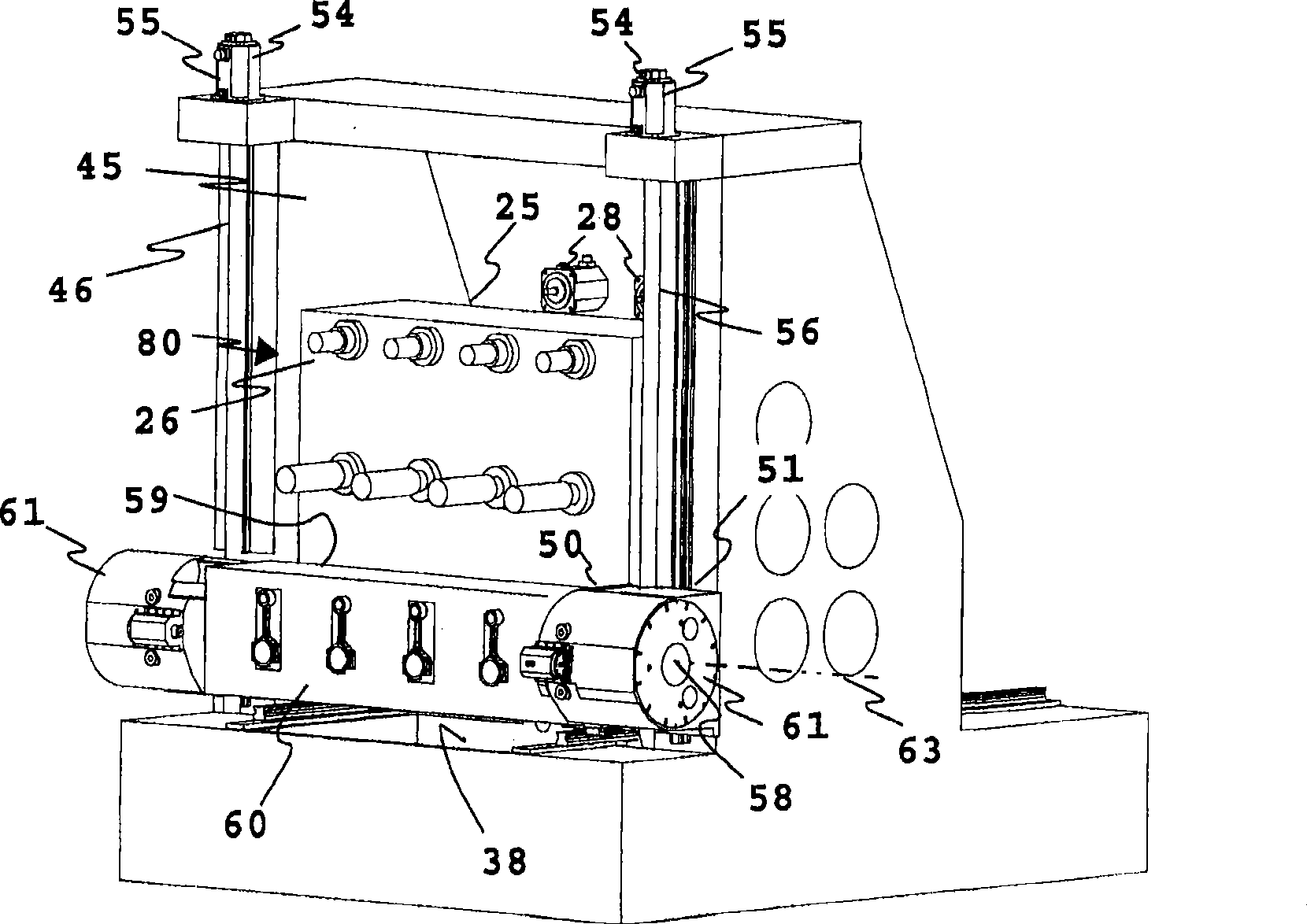
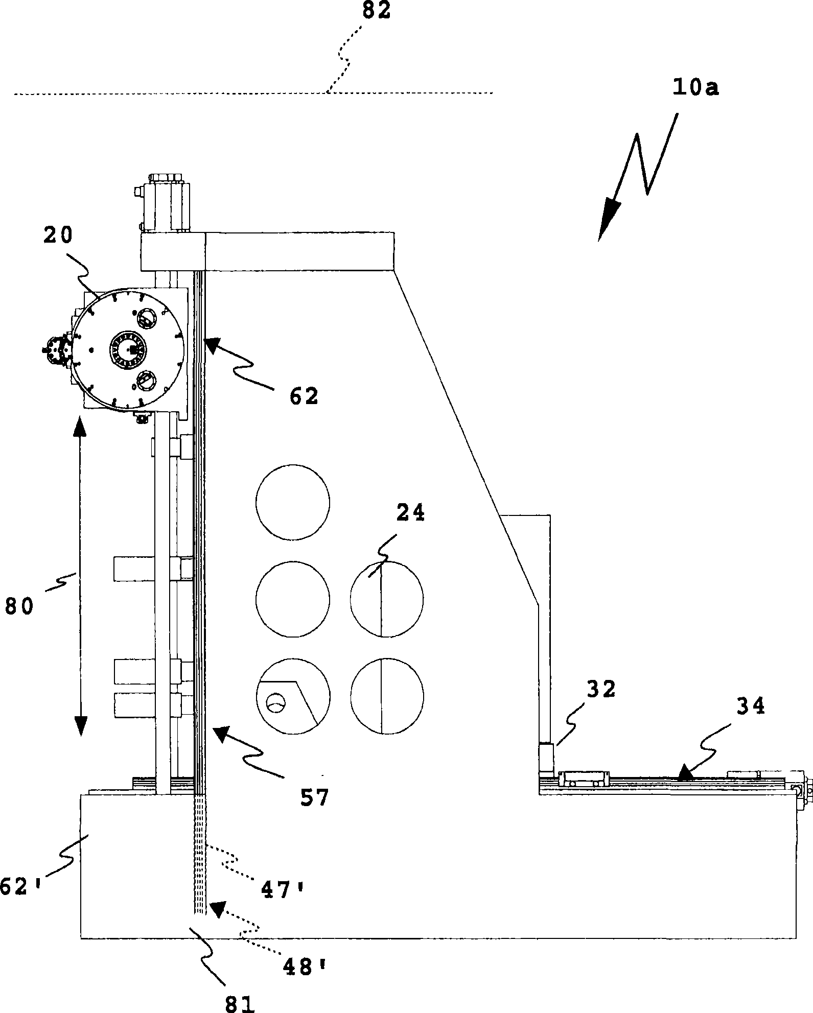
[0031] The multi-spindle machining center 10a is used for chip-forming machining of a workpiece 11, for example a connecting rod of an internal combustion engine. The multi-spindle machining center 10 a includes a spindle (or spindle) or a plurality of spindles 12 grouped together as a single spindle group 13 . Four spindles 12 are respectively arranged in each spindle row 14-17. Altogether, a total of four spindle rows 14-16, ie, twelve spindles 12, are shown. The spindles 12 in each spindle row 14 - 16 are in each case arranged horizontally in a straight line, however, arcuate row arrangements, row arrangements along zigzag lines etc. are also easily achievable. Furthermore, more or less than 12 spindles and more or less than 3 spindle rows are possible.

[0032] Chip forming tools 23 are mounted on the spindle 12, such as drilling and milling tools, lathe turning tools, and the like. A plurality of workpieces 11 can be machined simultaneously by means of the spindle 12 ....


PUM


Abstract

A multi-spindle machining center for the chip forming processing of workpieces comprises a spindle group having at least two spindles arranged in a spindle row adjacent to each other to mount a chip forming tool, and a workpiece support, on which at least two workpiece holders, correlated with the geometrical arrangement of the spindles, for holding workpieces for a simultaneous processing by means of the spindles, are arranged, the workpiece support having a beam-like longitudinal support member bearing the workpiece supports, and the spindles are guided for a movement toward the workpiece support in a first axial direction on a spindle linear guide arrangement. In the multi-spindle machining center there is a provision such that for positioning the workpieces in relation to the spindles workpiece support is guided on a workpiece support linear guide arrangement in a second axial direction running athwart the first axial direction and wherein the workpiece support is able to be shifted on the workpiece support linear guide arrangement in a servicing area arranged above or below the a working region of the spindles.

Description

technical field [0001] The present invention relates to a multi-spindle machining center for chip-forming processing of workpieces, said multi-spindle machining center comprising a spindle group having at least two spindles arranged adjacent to each other in a row of spindles for mounting chips, and a workpiece support forming the spindle of the tool, while at least two workpiece holders are arranged on said workpiece holder, said workpiece holders being related to the geometrical arrangement of said spindle, for holding a workpiece for simultaneous machining by means of said spindle, The workpiece support has a beam-like longitudinal support supporting the workpiece support, and the spindle is guided for movement on a spindle linear guide in a first axial direction towards the workpiece support. Background technique [0002] Such a multi-spindle machining center is described, for example, in European patent application 1695791. The workpiece holder is arranged in front of ...

Claims


Application Information

Patent Timeline
IPC IPC(8): B23Q1/01B23Q39/04
CPCB23Q2039/006B23Q39/024B23Q7/048Y10T483/1705Y10T409/305824Y10T409/305376Y10T29/5114Y10T409/308288Y10T409/309576Y10T409/307168Y10T408/385Y10T409/304088Y10T409/305768Y10T483/16
Inventor T·洛姆巴彻S·汉希
Owner ALFING KESSLER SONDERMASCH
Why Eureka
Try Eureka