Eureka AIR delivers breakthrough ideas for toughest innovation challenges, trusted by R&D personnel around the world.

Arrangement method of grass cutter barycenter

An arrangement method and technology of lawn mowers, applied in lawn mowers, harvesters, cutters, etc., can solve the problems of unfavorable traveling and mowing, poor adaptability, and large walking resistance, so as to improve grip, reduce resistance, The effect of increasing power

Inactive Publication Date: 2010-12-15
林正道
View PDF4 Cites 0 Cited by
  • Summary
  • Abstract
  • Description
  • Claims
  • Application Information

AI Technical Summary

Problems solved by technology

But its limitation is large walking resistance and poor adaptability, which is not conducive to walking and mowing on complex terrain and dense lawns

Method used


Image

  • Arrangement method of grass cutter barycenter
  • Arrangement method of grass cutter barycenter
  • Arrangement method of grass cutter barycenter

Examples


Embodiment Construction

[0019] Below in conjunction with accompanying drawing 3 to appendix Figure 6 Embodiments of the invention are illustrated:

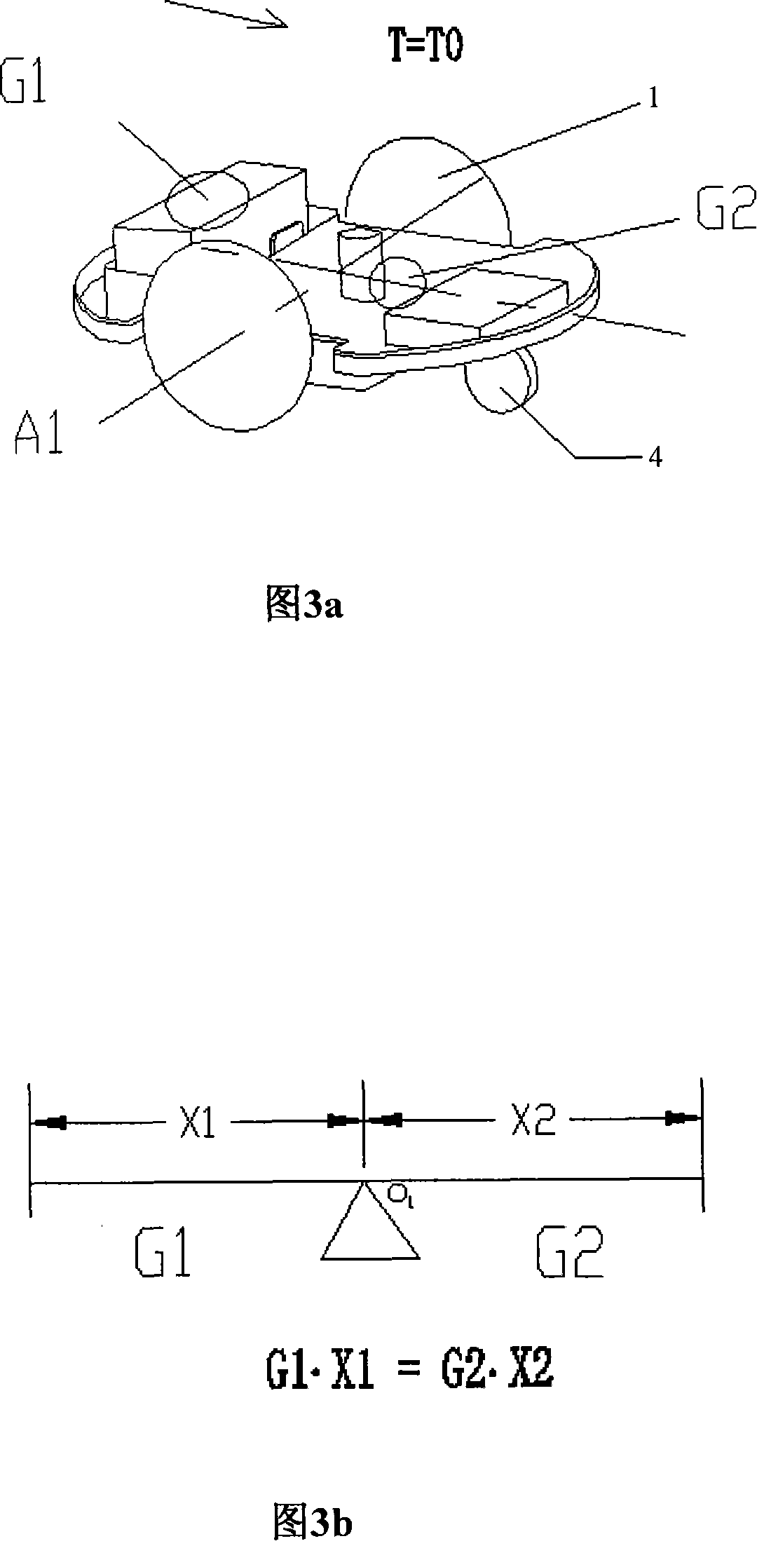
[0020] See attached Figure 3a , Figure 3b , to provide a typical case of the arrangement structure and method of the center of gravity of the lawnmower, which places the drive wheel of the lawnmower in the middle of the whole machine, the power supply, that is, the battery, behind the axis A1 of the drive wheel, and the drive motor in the center. The mowing motor is located in front of A1, and the driven guide wheel is placed in front of A1. The center of gravity of the whole machine falls on the drive wheel axle center line A1, namely G1X1=G2X2.

[0021] According to the center of gravity arrangement structure and method, it can be adjusted appropriately on this basis, so that the center of gravity of the whole machine falls on the position slightly in front of the driving wheel axis A1, that is, let G2X2≥GAX1. But G2X2-G1XA is controlled within ...


PUM


Abstract

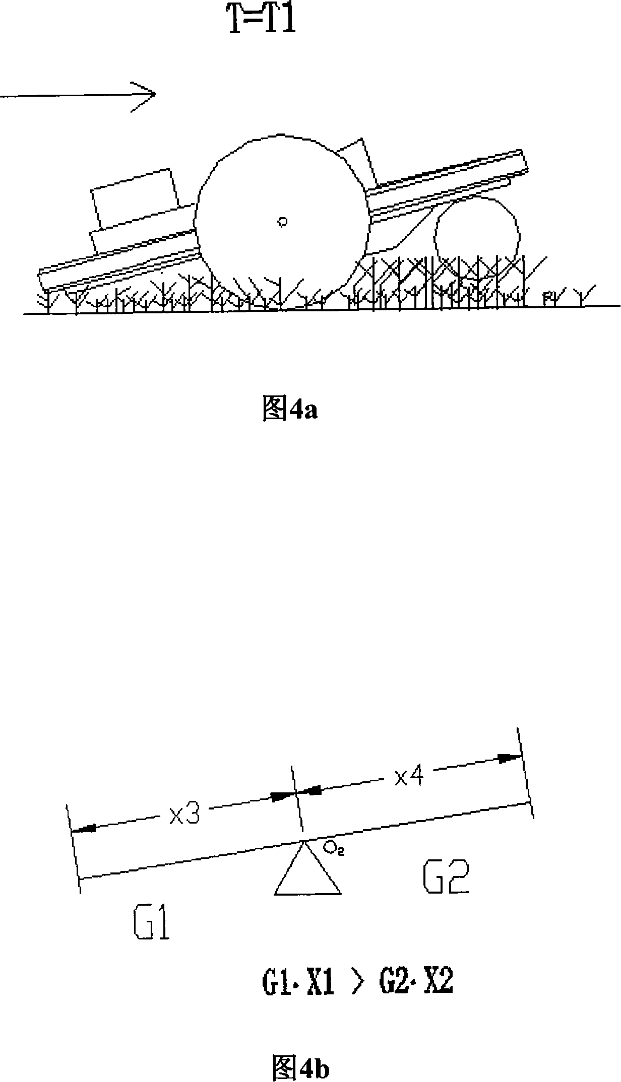
The invention provides a method for arranging a center of gravity of a mower. The method comprises the following steps: weight of the mower is divided into two parts which are respectively positioned on two sides of a wheel axis of a driving wheel, and the weights of the two parts reach an equilibrium state relative to moment of the wheel axis of the driving wheel; the weight of the whole mower is concentrated on two driving wheels; and a guide wheel is arranged in the front. The head part of the mower can automatically turn up and recover on the basis of the theory of dynamic equilibrium andresistance of a ground tussock when the mower moves so as to reduce the resistance while going ahead, which benefits guiding grass into a grass chopping chamber, improves the mowing effect and efficiency, is especially applicable to the small and light mower, such as a remote control mower, a fully automatic intelligent mower and the like.

Description

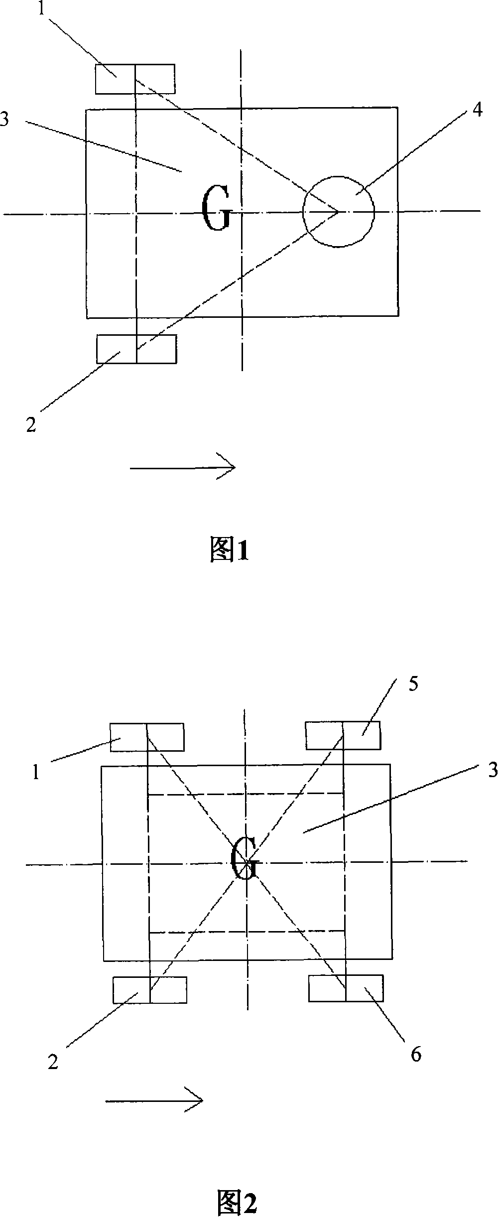
technical field [0001] The invention relates to a method for arranging the center of gravity of a lawnmower, which is suitable for remote control lawnmowers and fully automatic lawnmowers. Background technique [0002] At present, the structure of the arrangement of the center of gravity of the existing mower usually allows the center of gravity of the machine to fall inside the geometric pattern formed by the supporting wheels (points) (such as figure 1 shown), the most typical arrangement is to make the center of gravity of the whole machine coincide with the center of gravity of the geometric pattern formed by the support wheels (points) (such as figure 2 shown). Such center of gravity arrangement has simple structure, convenient installation and stable walking. However, its limitations are high walking resistance and poor adaptability, which are not conducive to walking and mowing on complex terrain and dense lawns. Contents of the invention [0003] The purpose of...

Claims


Application Information

Patent Timeline
Patent Type & Authority Patents(China)
IPC IPC(8): A01D34/00A01D101/00
Inventor 林正道
Owner 林正道
Why Eureka
Eureka Blog
Learn More