Air flow measuring instrument

A technology for flow measurement and fluid passage, applied in the field of flowmeters, can solve problems such as difficulty in achieving stable measurement, and achieve the effect of preventing damage or contamination

Inactive Publication Date: 2009-05-27
HITACHI ASTEMO LTD
View PDF2 Cites 19 Cited by
  • Summary
  • Abstract
  • Description
  • Claims
  • Application Information

AI Technical Summary

Problems solved by technology

[0006] In the prior art, although there is an effect of protecting the flow measuring element from dust, since the arrangement surface of the flow measuring element is hidden from the flow direction, Therefore, regarding the flow rate that should be measured, there is a problem that it is difficult to achieve stable measurement due to the separation vortex of the fluid, etc.

Method used


Image

  • Air flow measuring instrument
  • Air flow measuring instrument
  • Air flow measuring instrument

Examples


Embodiment Construction

[0021] The specific structure of the present invention is as follows.

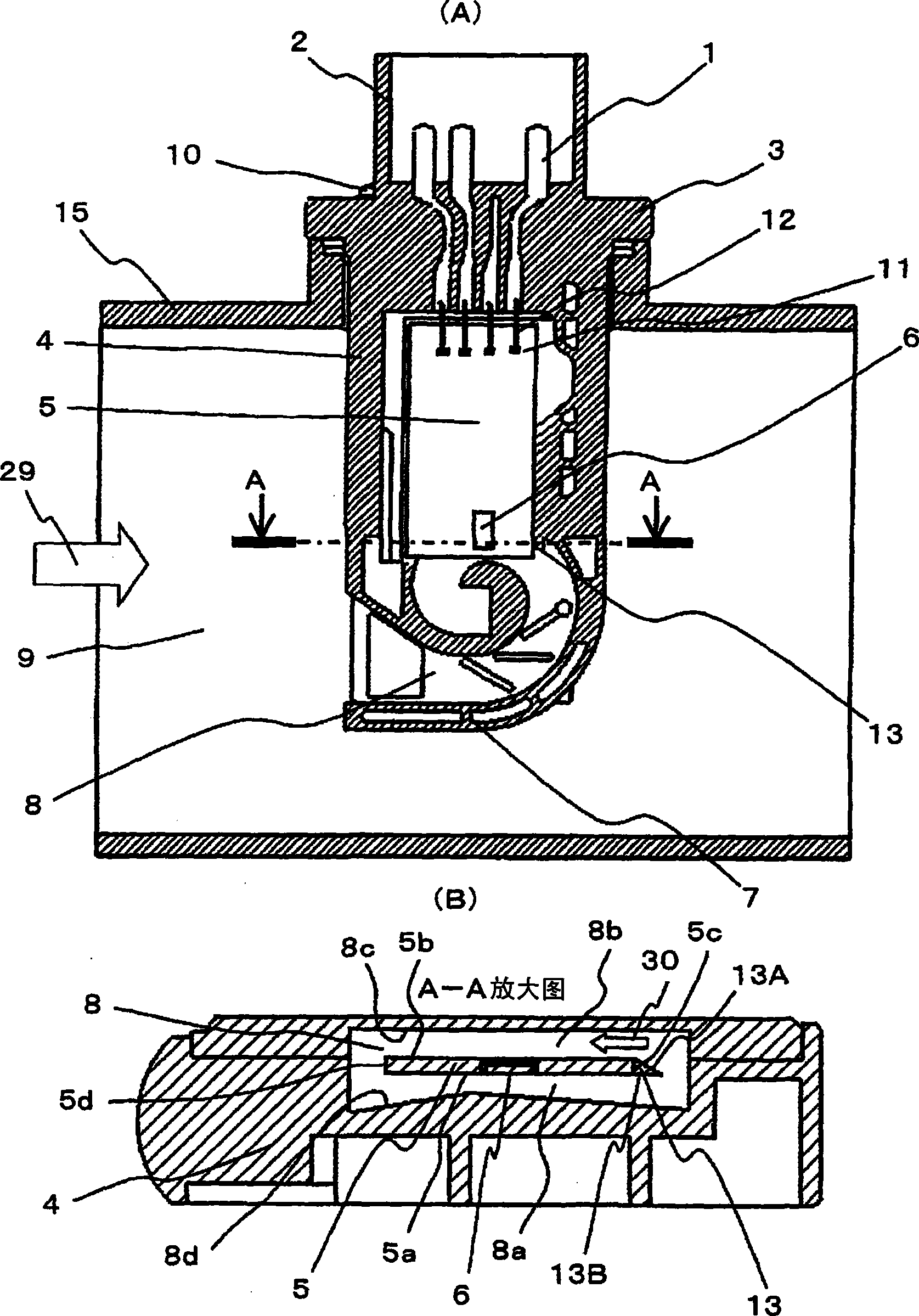
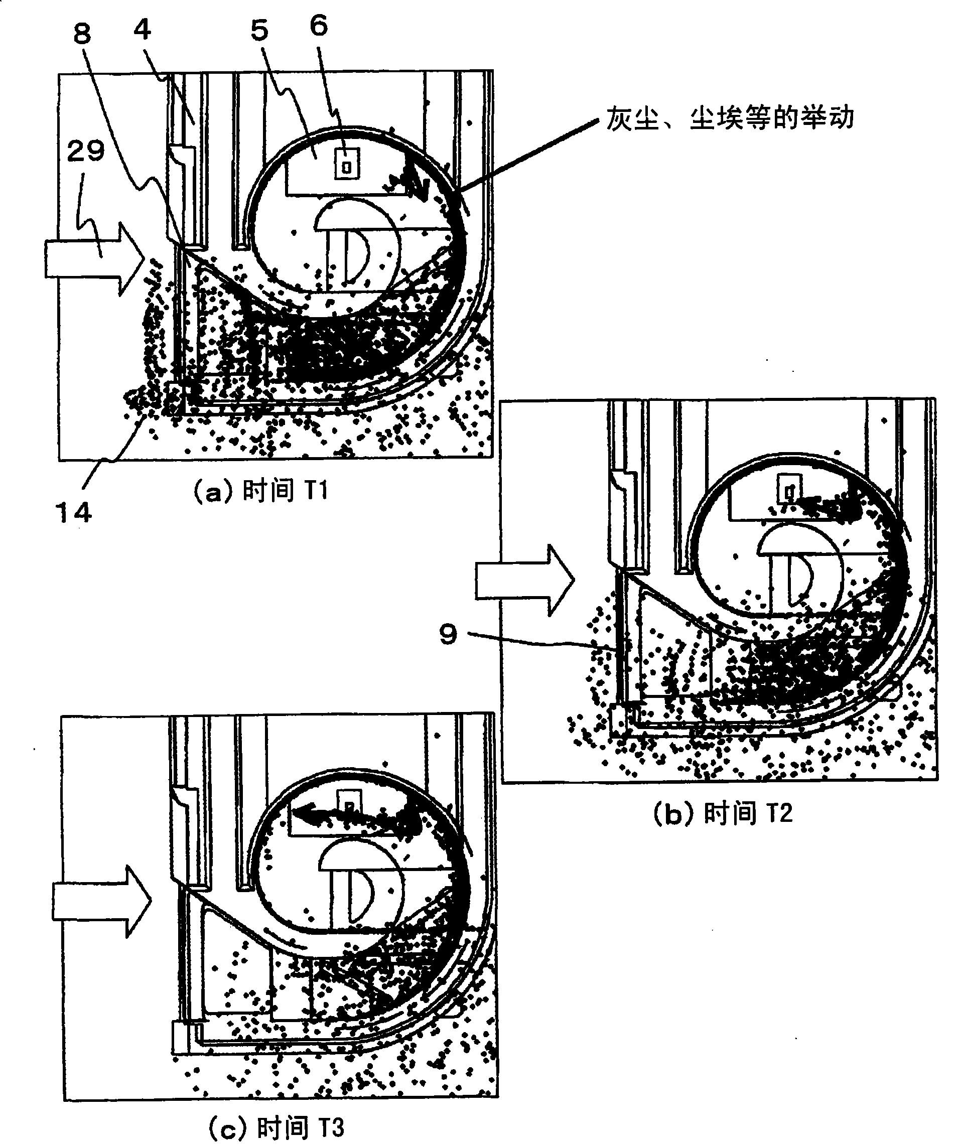
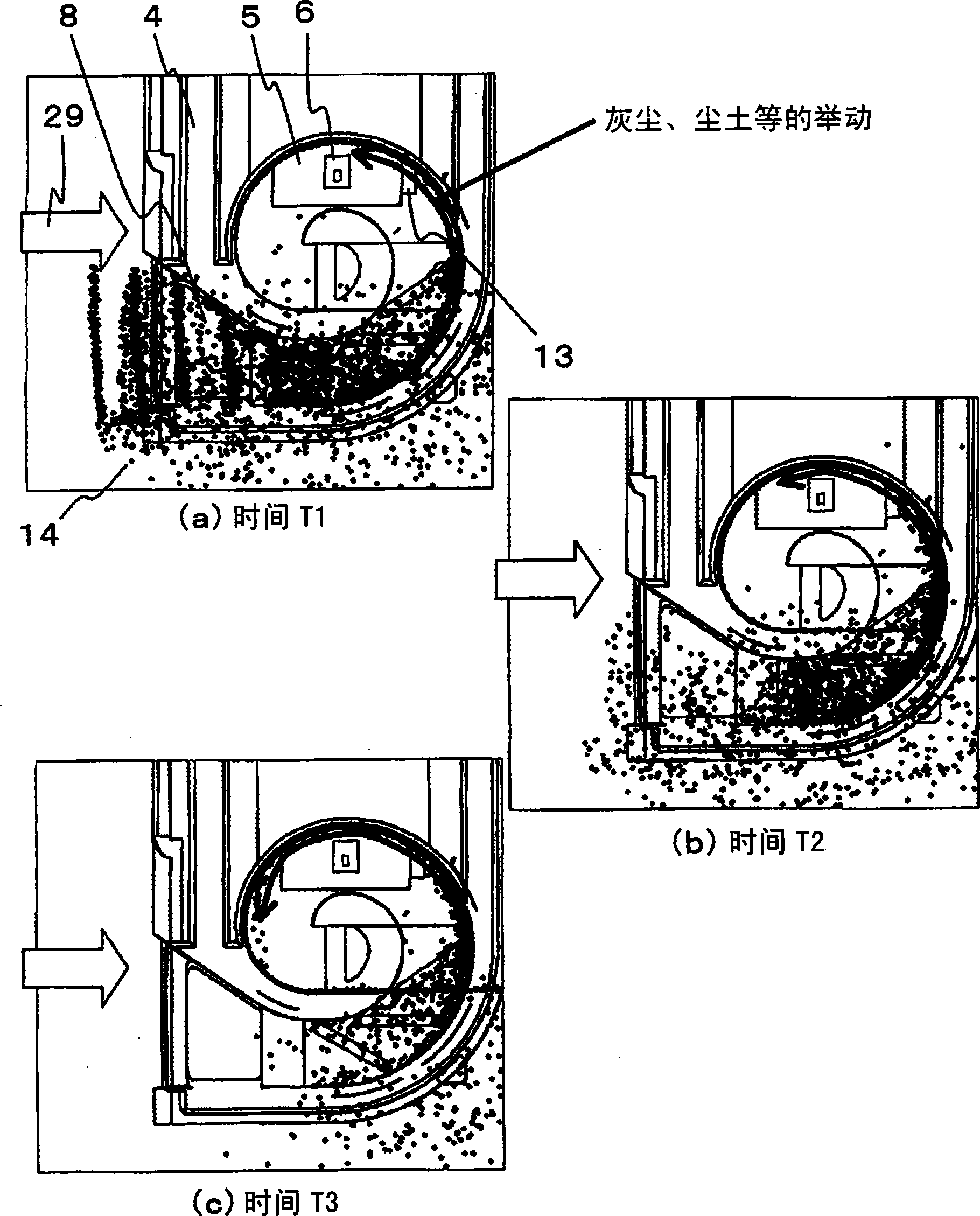
[0022] The present invention is a flow rate measuring device, which has a sub-path arranged in a main path through which fluid flows, and a plate-like member provided with a pattern of a heating resistor for measuring a flow rate on one side. , and the flat member is arranged in the sub-passage, the surface of the planar member provided with the pattern of the heating resistor is arranged along the flow of the fluid in the sub-passage, and in the flat part Between the surface of the member and the passage-forming surface of the sub-passage constitutes a heating resistor pattern-side fluid passage portion through which fluid flows, and between the surface of the flat member on the opposite side to the surface and the side of the sub-passage The back side fluid channel part is formed between the channel forming surfaces. In such a flow rate measurement device, an inclined surface is provided at the upstream ...


PUM


Abstract

The present invention is to prevent production loss because dust is sucked into a flow measuring element of an air flow measuring instrument for measuring air flow. The invention provides an air flow measuring instrument, comprising: an auxiliary passage 8 arranged inside a main passage 9 through which fluid flows, a tabular member 5 on which a pattern of a heating resistor for measuring an air flow is provided on one face 5a, the tabular member being disposed inside the auxiliary passage so that the one face 5a on which the heating resistor pattern of the tabular member is provided is disposed along a flow of fluid inside the auxiliary passage 8, a heating resistor pattern-side fluid passage 8a portion formed so that the fluid flows between the face 5a and a passage-forming surface 8d of the auxiliary passage, and a back-surface 8b side fluid passage portion formed so that fluid flows between a face 5b on a side opposite to the face of the tabular member and the passage-forming surface of the auxiliary passage. Guidance portion 13 guiding dust that collides against the end portion to back-surface side fluid passage portion 8b side is provided on upstream-side end of tabular member.

Description

technical field [0001] The present invention relates to a flow meter, in particular to a flow measurement device which constitutes an air intake system of an automobile engine and detects the air intake volume, thereby being more suitable for control. Background technique [0002] As a flow measuring device for measuring the air flow rate, a device that heats and controls a heating resistor to measure the flow rate by the amount of heat released from the heating resistor, and a device that heats and controls a heating resistor so that it passes through a temperature-sensitive resistor disposed near the heating resistor is known. A device that measures flow through changes in temperature. The flow measuring device is installed on a part of the intake pipe of the vehicle, and plays a role of measuring the flow rate of the intake air. Generally, an air filter is provided in the suction pipe, and dust contained in the air flowing into the suction pipe is removed by the air filt...

Claims


Application Information

Patent Timeline
Patent Type & Authority Applications(China)
IPC IPC(8): G01F1/69F02D41/18
CPCG01F15/12G01F5/00G01F1/6845
Inventor 斋藤直生森野毅冈本裕树半泽惠二鬼川博保川彰夫
Owner HITACHI ASTEMO LTD
Why Eureka
Try Eureka