
Racket holding device of racket threading machine

A technology of clamping device and threading machine, which is applied in the direction of threading rackets, rackets, sports accessories, etc., can solve the problems of racket frame deformation, lower racket yield, affect racket line density, racket line tightness, etc., to achieve Effect of reducing deformation error

Inactive Publication Date: 2011-01-12
黄淑娥
View PDF0 Cites 0 Cited by
  • Summary
  • Abstract
  • Description
  • Claims
  • Application Information

AI Technical Summary

Problems solved by technology

[0003] However, when threading is performed, the racket outer frame 1 is clamped by the fixing device 93, and then the racket is threaded. However, the tension of the string in the threading action can be regarded as the load on the racket string. During the process, the racket is partially threaded, that is, the racket is only partially loaded. At this time, it is easy to deform the frame of the racket due to uneven force. It will affect the density of the racket string on the racket and the tightness of the racket string, which will reduce the yield rate of the racket during the stringing operation

Method used


Image

  • Racket holding device of racket threading machine
  • Racket holding device of racket threading machine
  • Racket holding device of racket threading machine

Examples


Embodiment Construction

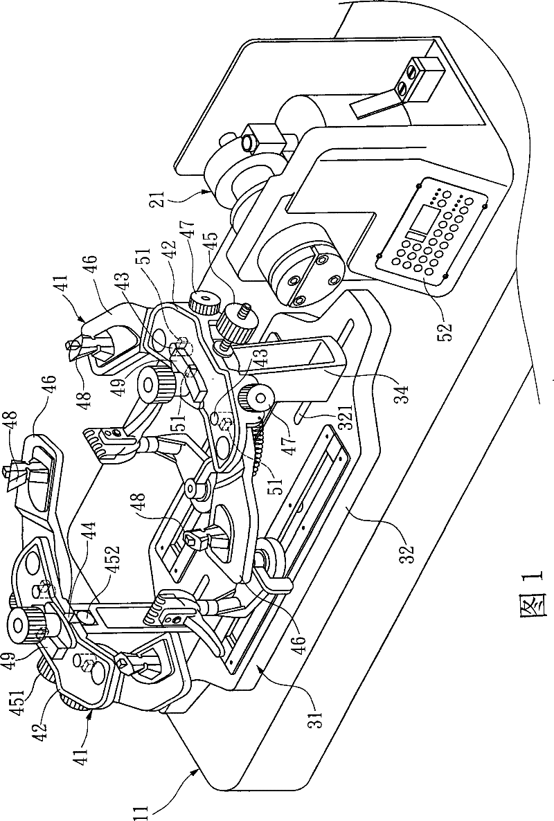
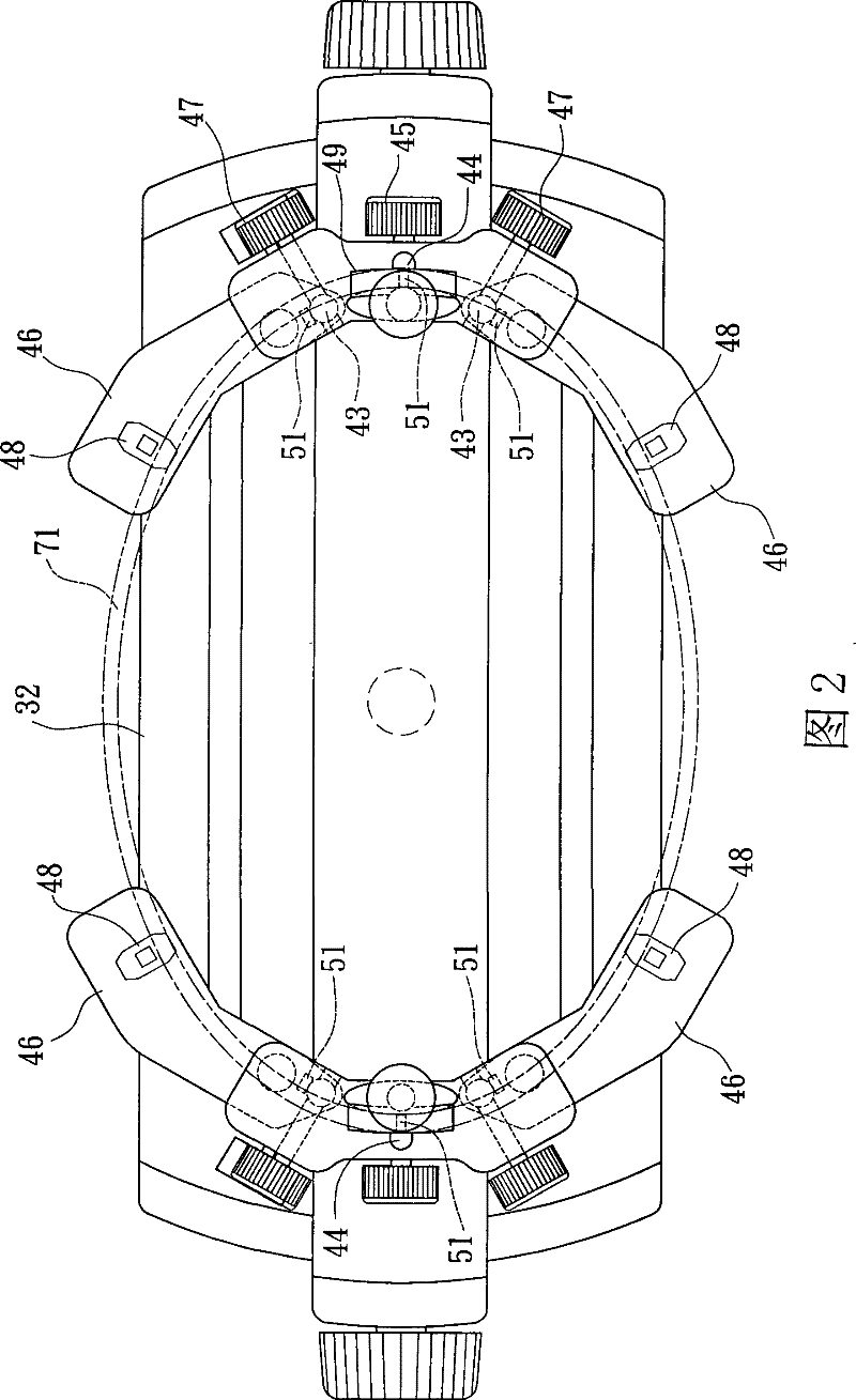
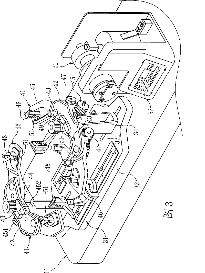
[0021] First please refer to figure 1 and figure 2 , the present invention relates to a racket clamping device for a racket stringing machine, the stringing machine includes a base 11, a wire pulling device 21 and a rotating table 31, one end of the base 11 is provided with a wire pulling device for controlling the tension of the racket string 21, the other end is a turntable 31 that can rotate horizontally; the turntable 31 includes a bottom plate 32, two movable frames 34 and two racket clamping devices 41, the bottom plate 32 is provided with a number of rail grooves 321, and the movable frame 34 is Located in the rail groove 321 , the movable frame 34 can move in the rail groove 321 and be fixed at a specific position of the bottom plate 32 , so that different distances between the two movable frames 34 can be used for rackets of different sizes.

[0022] The racket clamping device 41 is composed of a main body 42, two clamping arms 46, a hook 49, several sensors 51 and...


PUM


Abstract

A racket holding device of racket threading machine comprises a main body provided with a runner, two holding arms respectively arranged at the two sides of the main body and capable of adjusting the distance therebetween; a hooking component arranged in the runner of the main body and capable of moving in the runner; a predetermined number of sensors arranged on the racket holding device for sensing the deflection of the holding arms and hooking component in the holding process to generate sensing signals; and a control module used for summarizing the sensing signals generated by each sensor; therefore, the sensing signals summarized by the control module can determine the cable tension of the racket threading machine so as to reduce the deflection error of the racket in threading process.

Description

technical field [0001] The invention relates to a racket clamping device of a racket stringing machine. Background technique [0002] Existing racket stringing machines such as Figure 5 As shown, it is composed of a base 9, a backguy device (not shown) and a rotating table 91. One end of the base 9 is provided with a backguy device for controlling the tension of the racket string, and the other end is a horizontally rotatable Rotary table 91, this rotary table 91 is provided with two movable frames 92, is provided with two racket fixtures 93 on it, and it comprises a platform 94, a pressure frame member 96, a screw rod 97 and a knob 98, and this platform 94 There is a chute 95 on the top, for the racket fixing device 93 to do a small displacement, a screw rod 97 passes through the chute 95, a roughly rectangular parallelepiped pressure frame 96, and a knob 98, and the bottom of the screw rod 97 is bolted to the chute 95. Place a racket outer frame 1 between the pressing fr...

Claims


Application Information

Patent Timeline
Patent Type & Authority Patents(China)
IPC IPC(8): A63B51/14A63B51/16
Inventor 黄淑娥
Owner 黄淑娥
Learn More