
Drilling equipment for oil-immersed transformer machining

A technology for oil-immersed transformers and drilling equipment, which is applied in metal processing equipment, drilling/drilling equipment, metal processing, etc., and can solve the problems of reduced processing accuracy, reduced service life of linear drive devices, and increased wear of linear drive devices and other issues to achieve the effect of improving structural rigidity, improving machining accuracy, and reducing deformation errors

Pending Publication Date: 2021-03-16
江苏恒屹变压器股份有限公司
View PDF0 Cites 0 Cited by
  • Summary
  • Abstract
  • Description
  • Claims
  • Application Information

AI Technical Summary

Problems solved by technology

[0004] The purpose of the present invention is to provide a kind of drilling equipment for processing oil-immersed transformers, to solve the problem that the existing drilling equipment proposed in the above background technology is usually not equipped with waste cleaning equipment, and the waste produced by processing is easy to adhere to the workbench. surface, so that it needs to be cleaned manually in the next processing, and it is not convenient to use. The headstock of the existing drilling equipment usually needs multiple linear drive devices to adjust the position, and the vibration generated by the headstock during operation increases the linear drive device. Abrasion reduces the service life of the linear drive device, and the headstock of the existing drilling equipment has few supporting parts, resulting in a low structural rigidity of the headstock, and deformation after long-term use, resulting in reduced machining accuracy and affecting the finished product Workpiece quality issues

Method used


Image

  • Drilling equipment for oil-immersed transformer machining
  • Drilling equipment for oil-immersed transformer machining
  • Drilling equipment for oil-immersed transformer machining

Examples


Embodiment Construction

[0031] The following will clearly and completely describe the technical solutions in the embodiments of the present invention with reference to the accompanying drawings in the embodiments of the present invention. Obviously, the described embodiments are only some, not all, embodiments of the present invention. Based on the embodiments of the present invention, all other embodiments obtained by persons of ordinary skill in the art without making creative efforts belong to the protection scope of the present invention.

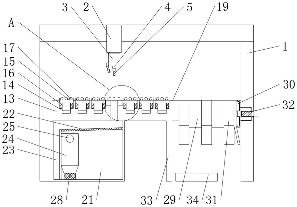
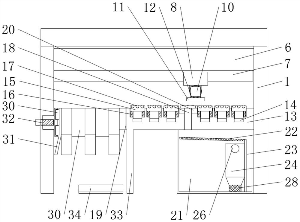
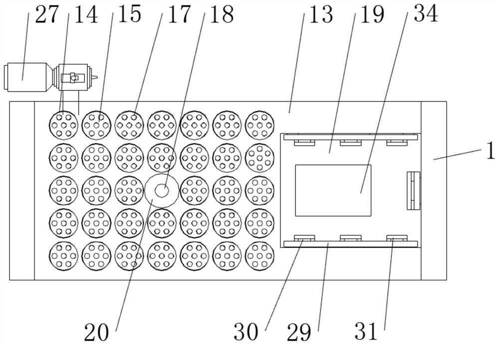
[0032] see Figure 1-7 , the present invention provides a technical solution: a drilling equipment for oil-immersed transformer processing, such as figure 1 , image 3 , Figure 5 and Image 6 As shown, the first hydraulic drive device 2 is fixedly installed on the top of the support 1, and the headstock 3 is fixedly installed on the bottom of the first hydraulic drive device 2. Drill bit 5, the centerline of drill bit 5 coincides with the centerline of th...


PUM


Abstract

The invention discloses drilling equipment for oil-immersed transformer machining. The drilling equipment for oil-immersed transformer machining comprises a support, a workbench, a recovery box and amovable plate, wherein a first hydraulic driving device is fixedly installed at the top of the support, and a spindle box is fixedly installed at the bottom of the first hydraulic driving device; a tool rest is rotatably installed at the bottom of the spindle box, and a drill bit is fixedly installed at the bottom of the tool rest; and a cross beam is fixedly welded to the front side of the support, and a linear motor is fixedly installed at the bottom of the cross beam. The drilling equipment for oil-immersed transformer machining is provided with an air extraction pump, the recovery box anda gas-water separator, the air extraction pump extracts air in the recovery box through the gas-water separator, under the action of negative pressure, air between the workbench and a workpiece carries waste to enter the recovery box through a through hole, cuttings are separated out through a filter screen and enter a waste cutting box, cutting fluid is separated out through the gas-water separator and left in the recovery box, the cuttings and the cutting fluid are automatically collected in a negative pressure suction mode, and secondary manual cleaning is not needed, so that more convenient use is achieved.

Description

technical field [0001] The invention relates to the technical field of drilling equipment, in particular to a drilling equipment for processing oil-immersed transformers. Background technique [0002] The case cover of the transformer is usually preset with a large number of through holes in order to facilitate the connection or communicate with the connecting pipe. In order to facilitate the batch processing of the through holes on the case cover, drilling equipment is required. [0003] The existing drilling equipment is usually not equipped with waste cleaning equipment, and the waste produced during processing is easy to adhere to the surface of the workbench, so that it needs to be cleaned manually in the next processing, which is not convenient to use. The headstock of the existing drilling equipment Usually, multiple linear drive devices are required to adjust the position, and the vibration generated during the operation of the headstock increases the wear of the lin...

Claims


Application Information

Patent Timeline
Patent Type & Authority Applications(China)
IPC IPC(8): B23B41/00B23Q1/01B23Q7/04B23Q11/00B25J15/06
CPCB23B41/00B23Q1/015B23Q11/0046B23Q7/04B25J15/0608
Inventor 刘兴慧
Owner 江苏恒屹变压器股份有限公司
Learn More