
Electric wave darkroom capable of carrying out acoustic testing and building method thereof

An anechoic chamber and acoustic testing technology, used in chemical instruments and methods, building components, laboratory utensils, etc. The problem of high construction cost can avoid repeated construction and save construction costs.

Active Publication Date: 2009-06-03
STATE GRID ELECTRIC POWER RES INST
View PDF0 Cites 13 Cited by
  • Summary
  • Abstract
  • Description
  • Claims
  • Application Information

AI Technical Summary

Problems solved by technology

[0004] Existing anechoic chambers and anechoic chambers have single functions. If a test product needs to be tested for acoustic and electromagnetic compatibility at the same time, it needs to be carried out in a special anechoic chamber and anechoic chamber. The construction cost of the anechoic chamber is very high, ranging from a few million to tens of millions. Considering that the anechoic chamber and the anechoic chamber have many similarities in the building structure, if the anechoic chamber is built, some sound absorption measures can be considered , allowing it to take into account the functions of the anechoic chamber and the anechoic chamber at the same time, which not only saves costs, but also avoids repeated construction, which has important practical significance for the current construction of a resource-saving and environment-friendly society
At present, there is no research anechoic room in the world that can conduct radio wave testing and acoustic testing at the same time. How to add sound absorption function to the key problem that needs to be solved on the basis of ensuring the function of the radio wave anechoic chamber

Method used


Image

  • Electric wave darkroom capable of carrying out acoustic testing and building method thereof
  • Electric wave darkroom capable of carrying out acoustic testing and building method thereof
  • Electric wave darkroom capable of carrying out acoustic testing and building method thereof

Examples


Embodiment Construction

[0016] The present invention will be described in further detail below in conjunction with the accompanying drawings and examples, but these examples should not be construed as limiting the present invention.

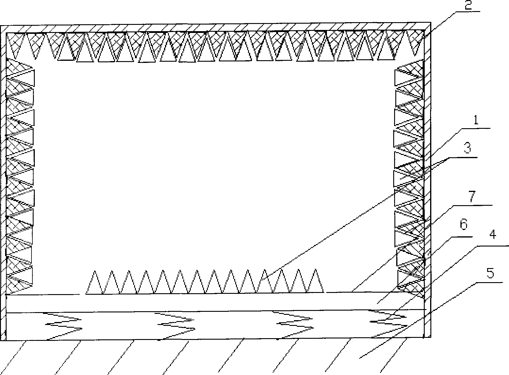
[0017] The present invention carries out the sound absorption design on the basis of a 10m anechoic chamber of 21m (L) * 14m (W) * 11m (H) (clear space).

[0018] The shielding body of this anechoic chamber adopts 3mm steel plate, and the absorbing material is a 2.4m wedge. Its specific steps are:

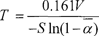
[0019] The first step: send the sample of the absorbing material to a professional acoustic testing organization for sound absorption performance testing: for the same material, the sound absorption increases with the increase of the frequency. , generally the most severe frequency point is used as the basis for assessment.

[0020] In this embodiment, the experimental assessment frequency is selected as 125Hz. The area of ​​the absorbing material sample is 44.1m 2 , the...


PUM


Abstract

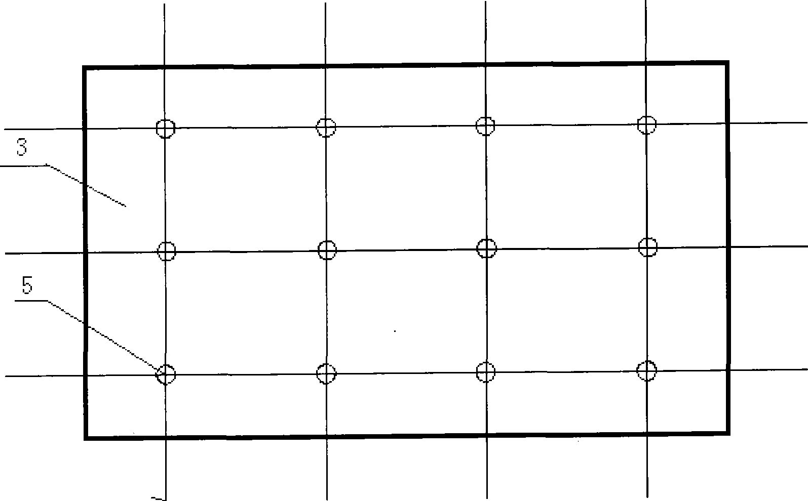
The invention relates to an anechoic chamber which is capable of carrying out acoustic testing, which comprises an anechoic chamber, and is characterized in that acoustic material is laid on the ground and / or the inner wall of the anechoic chamber; and a damping spring is further arranged on the ground of the anechoic chamber. The invention further provides a method for manufacturing the anechoic chamber capable of carrying out acoustic testing, which comprises the following steps: firstly, designing and mounting an anechoic chamber as required; then designing acoustic material and a sound-insulating structure according to the sound absorbing and acoustic insulating requirements of the anechoic chamber; and finally selecting and arranging a damping spring according to the total weight of the anechoic chamber. As the acoustic material and the sound insulating material are added to the prior anechoic chamber, the anechoic chamber has the advantage that not only the testing and research of electromagnetic compatibility, but also the testing and research of acoustic testing can be carried out, thereby avoiding repeated construction and greatly saving the cost of engineering construction.

Description

technical field [0001] The invention belongs to the field of electromagnetic compatibility of high-voltage power transmission and transformation engineering, and specifically relates to an electric wave anechoic chamber capable of acoustic testing and a construction method thereof. Background technique [0002] At present, the other five surfaces of the anechoic chamber except the ground are covered with wave-absorbing materials, which mainly simulate the open test site, that is, when the electric wave propagates, there are only direct waves and ground reflected waves, and at the same time, it shields external electromagnetic wave signals. American FCC, ANCI C63.6, Japan's VCCI, IEC, CISPR and other standards allow the use of electromagnetic shielding anechoic chambers instead of open test sites for EMC testing, mainly used for EMC testing of electrical, electronic products, and automobiles in the corporate world. [0003] The anechoic chamber can provide a low-noise test en...

Claims


Application Information

Patent Timeline
IPC IPC(8): B01L1/00E04B1/82
Inventor 邬雄张建功张小武万保权张广洲
Owner STATE GRID ELECTRIC POWER RES INST
Learn More