
Substrate capable of evenly distributing equidifferent voltage on surface and high visual-region resistance-type touch screen

A uniform distribution, touch screen technology, applied in the direction of electrical digital data processing, printed circuit components, electrical connection printed components, etc., can solve the problem that the voltage distribution cannot reach a certain level, the resistance uniformity has a great influence, and the accuracy of the click position To achieve the effect of increasing the area of ​​the visible area, uniform distribution of potential difference, and accurate feedback

Inactive Publication Date: 2009-06-03
OPTERA TECH XIAMEN
View PDF0 Cites 1 Cited by
  • Summary
  • Abstract
  • Description
  • Claims
  • Application Information

AI Technical Summary

Problems solved by technology

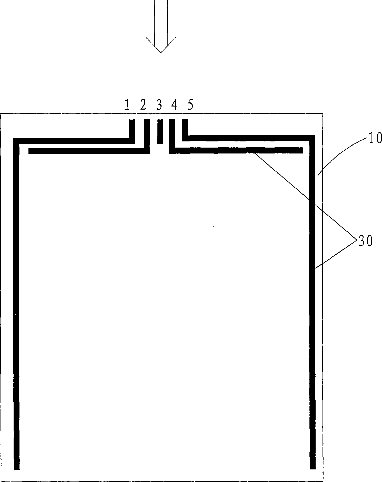
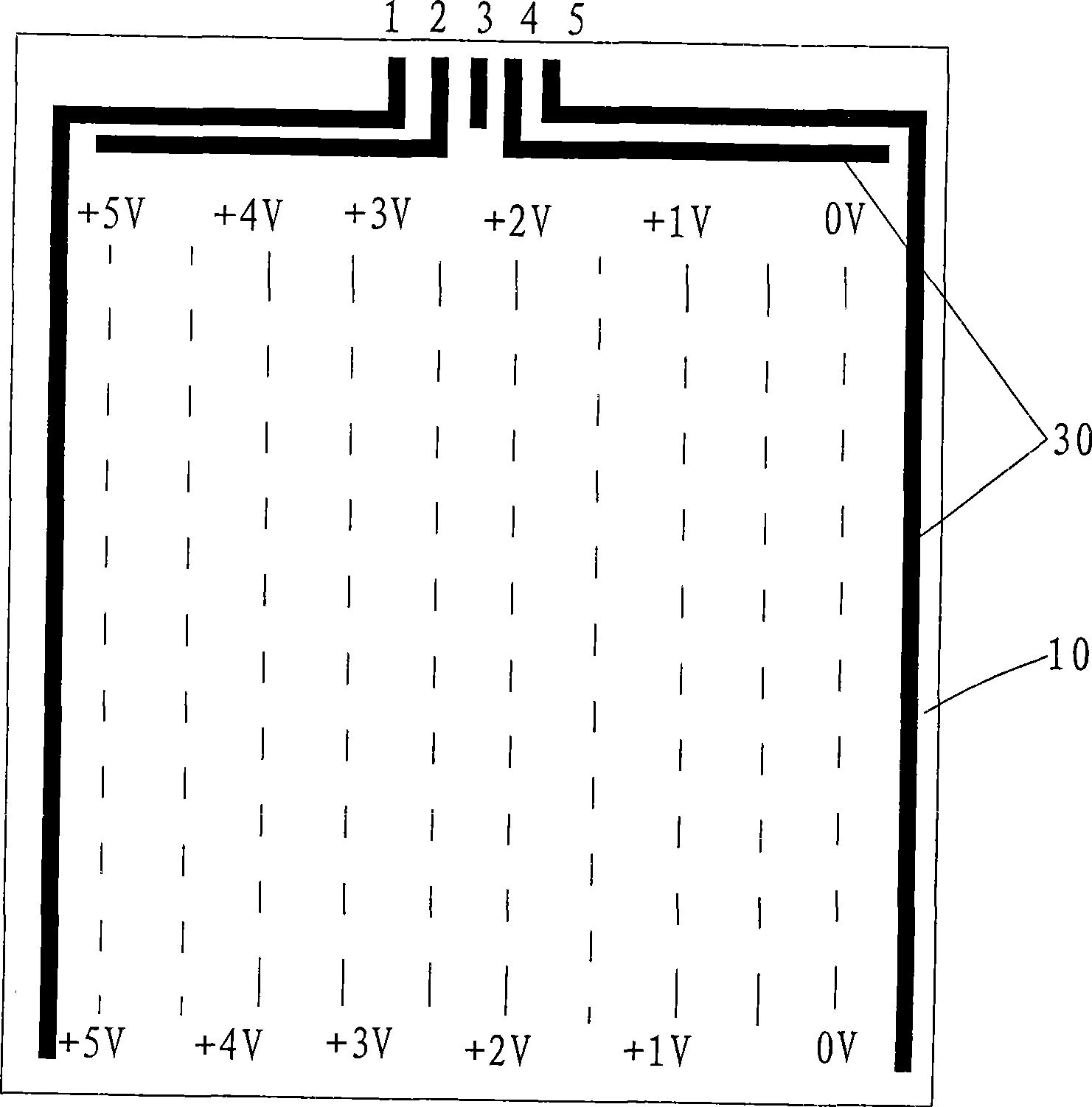
[0003] It can be seen that the circuit design of the general resistive touch screen is to make a single-layer conductive circuit structure on the edge of the substrate 10 to obtain the differential distribution voltage, so it has the following main defects: 1. The resistance uniformity of the edge of the substrate 10 is poor, and the voltage The distribution cannot reach a certain level, and the edge line space L of the touch screen must be controlled at about 20 millimeters (mm), such as Figure 5 As shown, resulting in a small viewing area 60;
[0004] 2. The single-layer circuit structure, the voltage distribution is mainly determined by the uniformity of the resistance of the substrate 10. This structure is greatly affected by the uniformity of the resistance of the substrate 10, resulting in poor accuracy of the click position, that is, the actual click position is different from the signal feedback position. Relatively large gap, generally around + / -5mm

Method used


Image

  • Substrate capable of evenly distributing equidifferent voltage on surface and high visual-region resistance-type touch screen
  • Substrate capable of evenly distributing equidifferent voltage on surface and high visual-region resistance-type touch screen
  • Substrate capable of evenly distributing equidifferent voltage on surface and high visual-region resistance-type touch screen

Examples


Embodiment Construction

[0038] like Image 6 , 7 As shown, the substrate 10 disclosed by the present invention, which can evenly distribute the differential voltage on the surface, is to arrange at least one layer of discontinuous wires 40 in the form of disconnection on the edge of the substrate 10 . The symmetrical distribution of the discontinuous wires 40 refines the circuit, which can make the distribution of the potential difference more uniform and achieve the purpose of equalizing the voltage. The voltage distribution is mainly affected by the design of the conductive circuit, which greatly reduces the influence of the uniformity of the edge ITO resistance on the voltage distribution.

[0039] Applying this structure to a resistive touch screen with a high viewing area can provide more accurate feedback on the click position of the touch screen and expand the area of ​​the viewing area.

[0040] The application of the substrate 10 of the present invention in a resistive touch screen with a h...


PUM


Abstract

The invention discloses a substrate capable of evenly distributing equidifferent voltage on the surface. At least one layer of intermittent leads are arranged at the margin of the substrate through an opened way, and the substrate can improve the evenness of voltage equidifferent distribution. The invention also discloses a high visual-region resistance-type touch screen which applies the substrate and comprises the substrate, a top plate, four power input ends connected with the substrate and a signal output end connected with the top plate, wherein, leads of a pinpoint 1 and a pinpoint 5 of the input ends are distributed at the margins of two sides of the substrate, leads of a pinpoint 2 and a pinpoint 4 are distributed at the upper margin of the substrate, and at least one layer of intermittent leads are also distributed at the lower margin of the substrate between the pinpoint 1 and the pinpoint 5, at least one intermittent leads are also distributed on the margins of two sides of the substrate between the leads of the pinpoint 2 and the pinpoint 4 and the intermittent leads at the lower margin of the substrate, and at least one layer of leads are also distributed at the upper margin of the substrate between the intermittent leads at the margin of two sides of the substrate. The structure of the invention can enlarge the visual-region area and improve the click definition.

Description

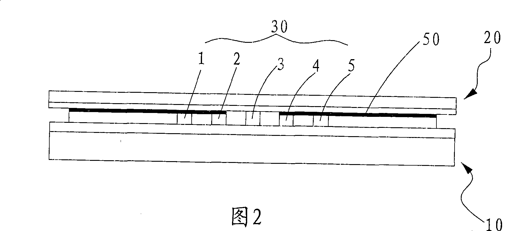
technical field [0001] The invention belongs to the technical field of touch screens and relates to the improved design of substrate circuits of resistive touch screens. Background technique [0002] In the prior art, a resistive touch screen includes a substrate 10 [including ITO (indium tin oxide) glass] and a top plate 20 [ITO conductive organic plate material PET, etc.], such as figure 1 As shown in FIG. 2 , the circuit design on the general substrate 10 has four power input ends (pin point 1, pin point 2, pin point 4, pin point 5) and a signal output end (pin point 3), the signal output terminal (pin point 3) is connected to the top plate 20, and the wires 30 drawn from the two power input terminals (pin point 1 and pin point 5) are arranged on both sides of the substrate 10, and the two power input terminals (pin point 2 and pin point 4) Lead wires 30 are laid on the upper edge of the base plate 10 , and insulating spacers 50 are provided between the four power input ...

Claims


Application Information

Patent Timeline
IPC IPC(8): G06F3/045H05K1/11
Inventor 章旭林越展
Owner OPTERA TECH XIAMEN
Learn More