High-stability heavy-load clamp

A high-stability, clamping technology, applied in the direction of collets, manipulators, manufacturing tools, etc., can solve problems such as high rotation speed of clamps, inconsistent forging deflection angles, and reduced pre-tightening clamping force, so as to improve production efficiency , smooth rotation, avoid weakening effect

Inactive Publication Date: 2011-04-13
CENT SOUTH UNIV
View PDF0 Cites 1 Cited by
  • Summary
  • Abstract
  • Description
  • Claims
  • Application Information

AI Technical Summary

Problems solved by technology

[0012] Excessive deflection angle causes the forging to fail when the deflection angle continues to increase when the clamp is lifted and rotated
[0013] Figure 6 is a schematic diagram of the clamp when it is clamped horizontally. Because the actual average working tension at the jaws is not equal when clamping horizontally and vertically; and because the deflection stiffness of the jaws is different when clamping horizontally and vertically, resulting in Make the deflection angle of the forging inconsistent, when the clamp rotates, the inertial force of the center of mass of the forging fluctuates, resulting in unstable clamping
[0014] In addition, if the rotation speed of the clamp is too high, the components of the clamping mechanism, especially the clamp head, will generate a large centrifugal force, which will reduce the pre-tightening clamping force and cause the clamping to fail.

Method used


Image

  • High-stability heavy-load clamp
  • High-stability heavy-load clamp
  • High-stability heavy-load clamp

Examples


specific Embodiment approach

[0035] The present invention finds out a method for improving the load-bearing capacity, load-bearing space and clamping stability of the clamp by utilizing the reaction force response blind area through in-depth research on the clamping mechanism and force flow transmission law of the clamp; and through the clamp mechanism The size and structure are optimized to provide a high-stability heavy-duty clamp. The specific implementation is as follows:

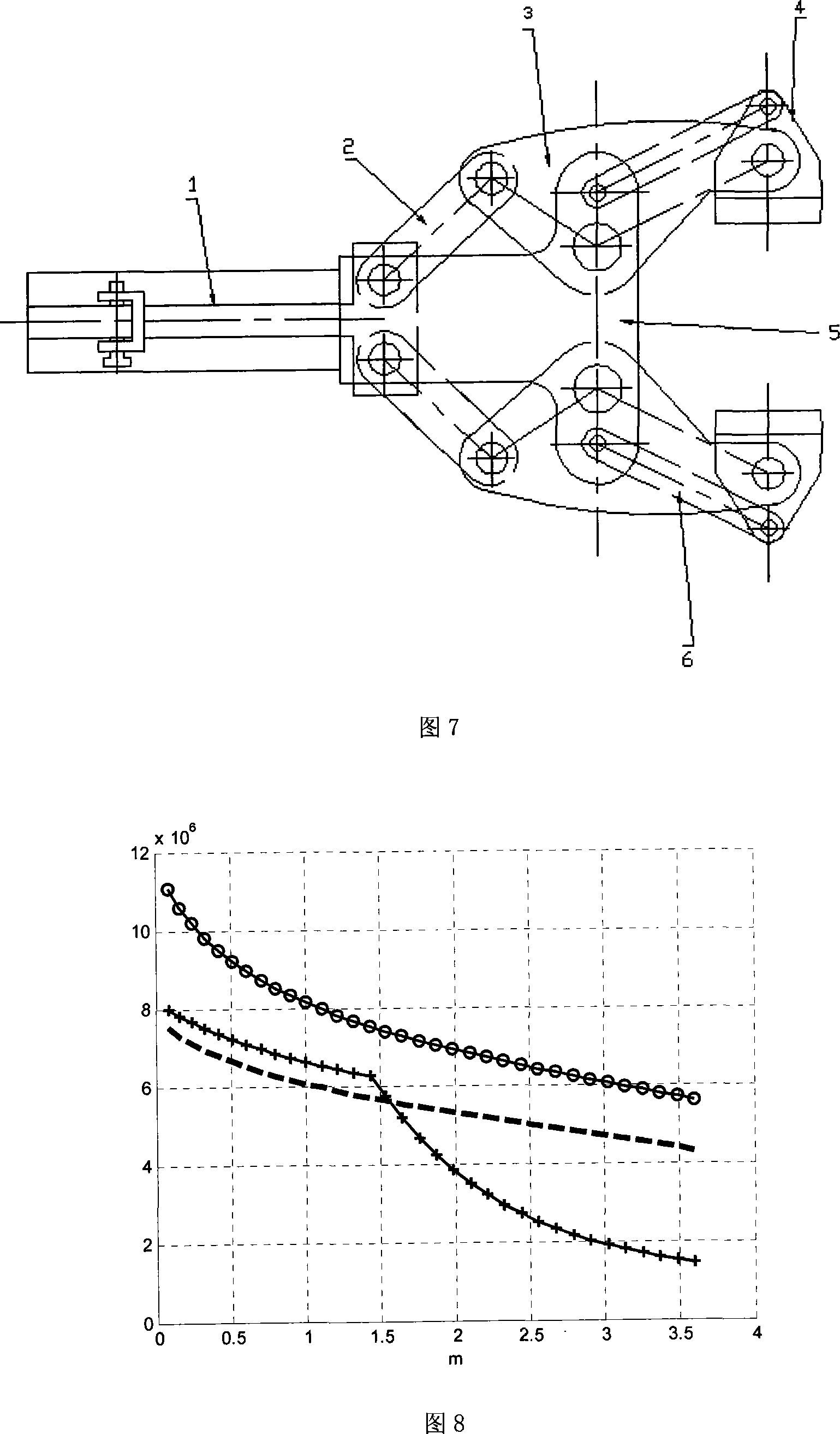
[0036] The clamp is composed of a push rod 1, a connecting rod 2, a clamp arm 3, a clamp head 4, a frame 5 and a pull rod 6, as shown in Fig. 7, wherein the clamp arm 3, the clamp head 4, the frame 5 and the pull rod 6 form a parallel The quadrilateral mechanism, and the hinge between the pull rod 6 and the clamp 4 leaves a certain gap, which can not only ensure the horizontal position of the clamp head 4, increase the vertical deflection stiffness of the jaw, but also enable the jaw to have a certain degree of mobility, To accomm...


PUM


Abstract

The invention provides a high stability heavy-duty clamp, which consists of a pushing rod 1, connecting rods 2, clamp arms 3, clamp heads 4, a stander 5 and pulling rods 6, wherein the clamp arms 3, the clamp heads 4, the stander 5 and the pulling rods 6 form a parallelogram mechanism. When the opening amount of a clamp mouth changes, the clamp heads 4 always keeps at a horizontal position to limit the declination angle of a forging piece in the vertical clamping so as to improve the clamping stability of the clamp; the pulling rods 6 of the clamp bears most of the loading torque, reduces the actual work tension and improves the bearing capability of the clamp by more than one time accordingly; the clamp improves the bearing capability by more than 29 percent by using the property of the response blind area of reaction force; and the clamp makes the centrifugal force produced by the front arm parts ( front arms of the clamp arms 3, the clamp heads 4 and the pushing rods 6) and the rear arm parts ( rear arms of the clamp arms 3 and the connecting rods 2) counteract by structure balance, and avoids weakening the pre-tightening holding force by the centrifugal force, so the clamp not only can ensure the clamping stability, but also can rotate quickly to improve the operating speed of the heavy-duty forging machine and improve the production efficiency.

Description

technical field [0001] The invention relates to a high-stability heavy-duty clamp, which is an executive component of a large-scale forging manipulator and a loading and unloading machine. , transportation and stacking, and clamping molds or tools for operation. Background technique [0002] Clamps are one of the key parts of large-scale heavy-duty operating equipment. It is required to ensure the stability of clamping during the lifting and rotation of large components under time-varying heavy-load conditions. Therefore, it is particularly important to invent a new type of high-stability heavy-duty clamp by comprehensively analyzing the load-bearing capacity, load-bearing space and stability of the large-scale clamp mechanism, and optimizing the size and structure of the clamp mechanism. [0003] Figure 1 is a schematic diagram of the pre-tightening clamping when the tongs just clamp the forgings placed on the workbench. It can be seen from Figure 2 that when the clamp is...

Claims


Application Information

Patent Timeline
Patent Type & Authority Patents(China)
IPC IPC(8): B21J13/10B25J15/00
Inventor 何竞飞邓华王艾伦李群明夏毅敏
Owner CENT SOUTH UNIV
Why Eureka
Try Eureka