Hybrid drive system and method

A driving system and hybrid power technology, which is applied to the arrangement of multiple different prime movers of the power plant, the general power plant, and the air pressure power plant, etc., can solve the problems of not fully considering the fuel economy of the engine, and achieve a reduction The effect of fuel consumption

Active Publication Date: 2009-06-10
BYD CO LTD
View PDF6 Cites 50 Cited by
  • Summary
  • Abstract
  • Description
  • Claims
  • Application Information

AI Technical Summary

Problems solved by technology

However, in USP5,433,282, the fuel economy prob

Method used


Image

  • Hybrid drive system and method
  • Hybrid drive system and method

Examples


Embodiment Construction

[0014] The present invention will be described in detail below through specific embodiments.

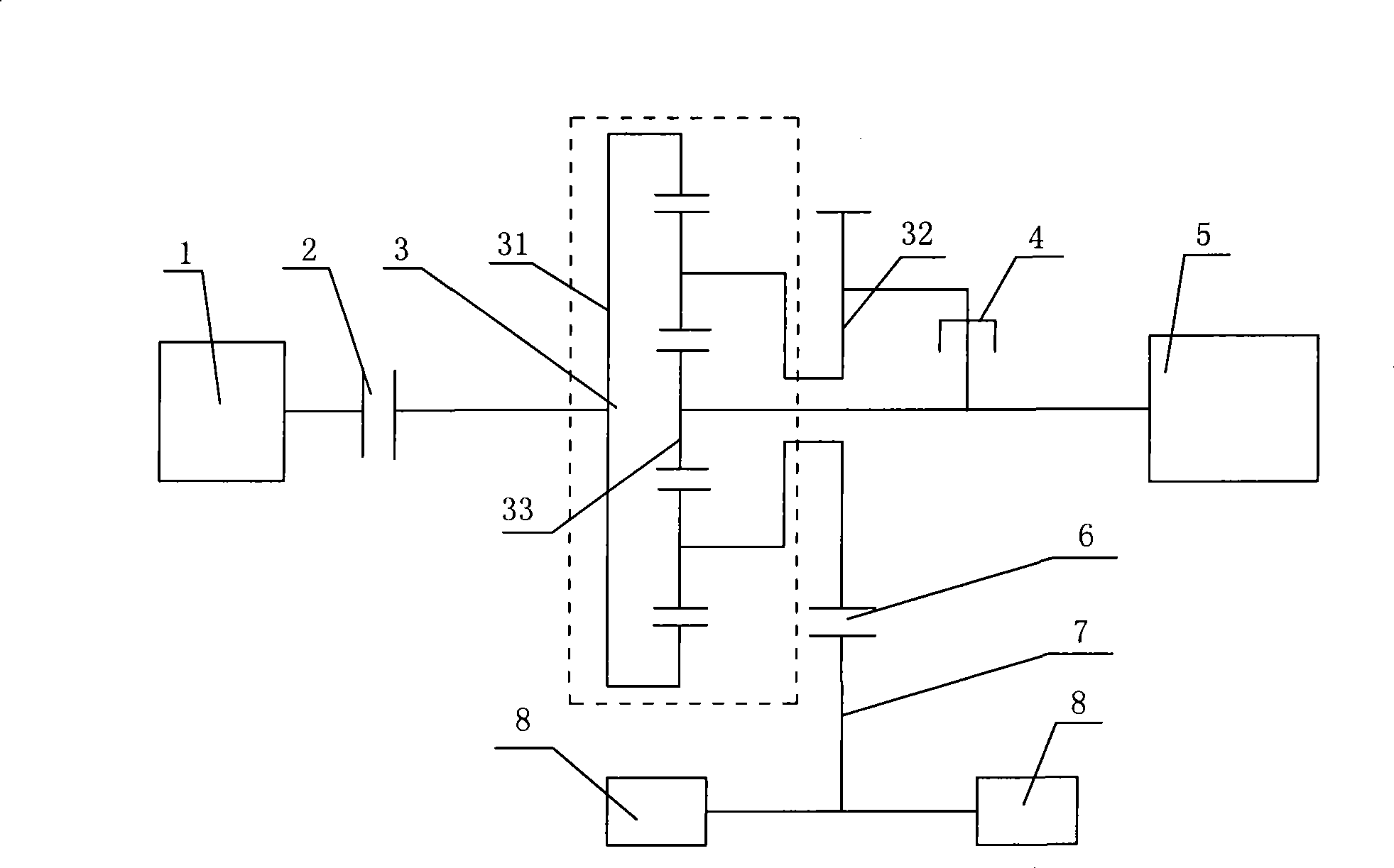
[0015] Such as figure 1 As shown, the present invention provides a hybrid drive system, which mainly includes an engine 1 , a motor 5 , a planetary gear mechanism 3 and a wheel drive shaft 7 .

[0016] The planetary gear mechanism 3 generally includes a first rotating element 31 , a second rotating element 32 and a third rotating element 33 . The first clutch 2 is arranged between the output shaft of the engine 1 and the first rotary element 31 , and the second clutch 6 is arranged between the wheel drive shaft 7 and the second rotary element 32 .

[0017] As shown in the figure, as a specific example, the first rotating element 31 is a ring gear; the second rotating element 32 is a planet carrier; and the third rotating element 33 is a sun gear. The ring gear 31 can be connected with the output shaft of the engine 1 through the first clutch 2 . The planet carrier 32 can be connec...


PUM


Abstract

The invention provides a hybrid power drive system, which comprises an engine, a motor, a planetary gear mechanism and a wheel drive shaft, wherein the planetary gear mechanism comprises a first rotting element, a second rotating element and a third rotating element; the first rotating element is connected to an output shaft of the engine; the second rotating element is connected to the wheel drive shaft; and the third rotating element is connected to the output shaft of the motor. The system also comprises a first clutch and a second clutch, wherein the first clutch is arranged between the output shaft of the engine and the first rotating element of the planetary gear mechanism; and the second clutch is arranged between the wheel drive shaft and the second rotating element of the planetary gear mechanism. The invention also provides a method for driving the hybrid power drive system. Under various drive modes, according to the rotating speed relation of the three rotating elements of the planetary gear mechanism, through control of the rotating speed of the motor, the rotating speed of the engine can be controlled, and the engine always runs in an oil consumption economical area, thereby reducing the oil consumption of the engine to the maximum.

Description

technical field [0001] The invention relates to the field of hybrid electric vehicles, in particular to a hybrid electric driving system and a driving method thereof. Background technique [0002] USP 5,433,282 discloses a hybrid vehicle driven by an engine and an electric motor, including an engine, an electric motor, a transmission and a wheel drive shaft. The transmission includes a planetary gear mechanism having first to third rotation elements and a one-way clutch. The first rotating element (such as the sun gear) of the planetary gear mechanism is connected to the output shaft of the engine, the second rotating element (such as the ring gear) is connected to the output shaft of the motor, and the third rotating element (such as the planet carrier) is connected to the wheel drive shaft . The one-way clutch is arranged between the first rotating element and the engine to ensure that the engine rotates in one direction and avoid dragging the engine to reverse when the ...

Claims


Application Information

Patent Timeline
IPC IPC(8): B60K6/365B60K6/387F16H3/72F16H61/32
Inventor 王传福罗红斌陈伟张晓玲
Owner BYD CO LTD
Why Eureka
Try Eureka