
Bridge expansion joint device preventing extra large vertical rotation angle displacement

A technology for expansion joints and bridges, applied in bridges, bridge parts, bridge construction, etc., can solve problems such as corner displacement, beam end upturning, expansion joint device damage, etc., to prevent breakage, avoid damage, and pass smoothly and safely Effect

Active Publication Date: 2009-06-10
徐斌
View PDF2 Cites 11 Cited by
  • Summary
  • Abstract
  • Description
  • Claims
  • Application Information

AI Technical Summary

Problems solved by technology

[0005] However, if the existing bridge expansion joint device is directly applied to other types of bridges with steel box girders on both sides or other types of bridges with large vertical displacement, and the beams are under the action of vehicle load , will produce deflection deformation, beam end upturning or sinking, and vertical corner displacement. Yes, the end of the comb teeth of the movable comb plate will be upturned relative to the beam body and conflict with the surface of the beam body. If the vehicle is under heavy pressure at this time, the entire expansion joint device will be damaged, which will seriously affect the safe passage of the vehicle.
Therefore, for bridges with relatively large vertical displacement of beams on both sides, the existing bridge expansion joint devices cannot be well applied.

Method used


Image

  • Bridge expansion joint device preventing extra large vertical rotation angle displacement
  • Bridge expansion joint device preventing extra large vertical rotation angle displacement
  • Bridge expansion joint device preventing extra large vertical rotation angle displacement

Examples


Embodiment Construction

[0020] The present invention will be further described in detail below in conjunction with the accompanying drawings and embodiments.

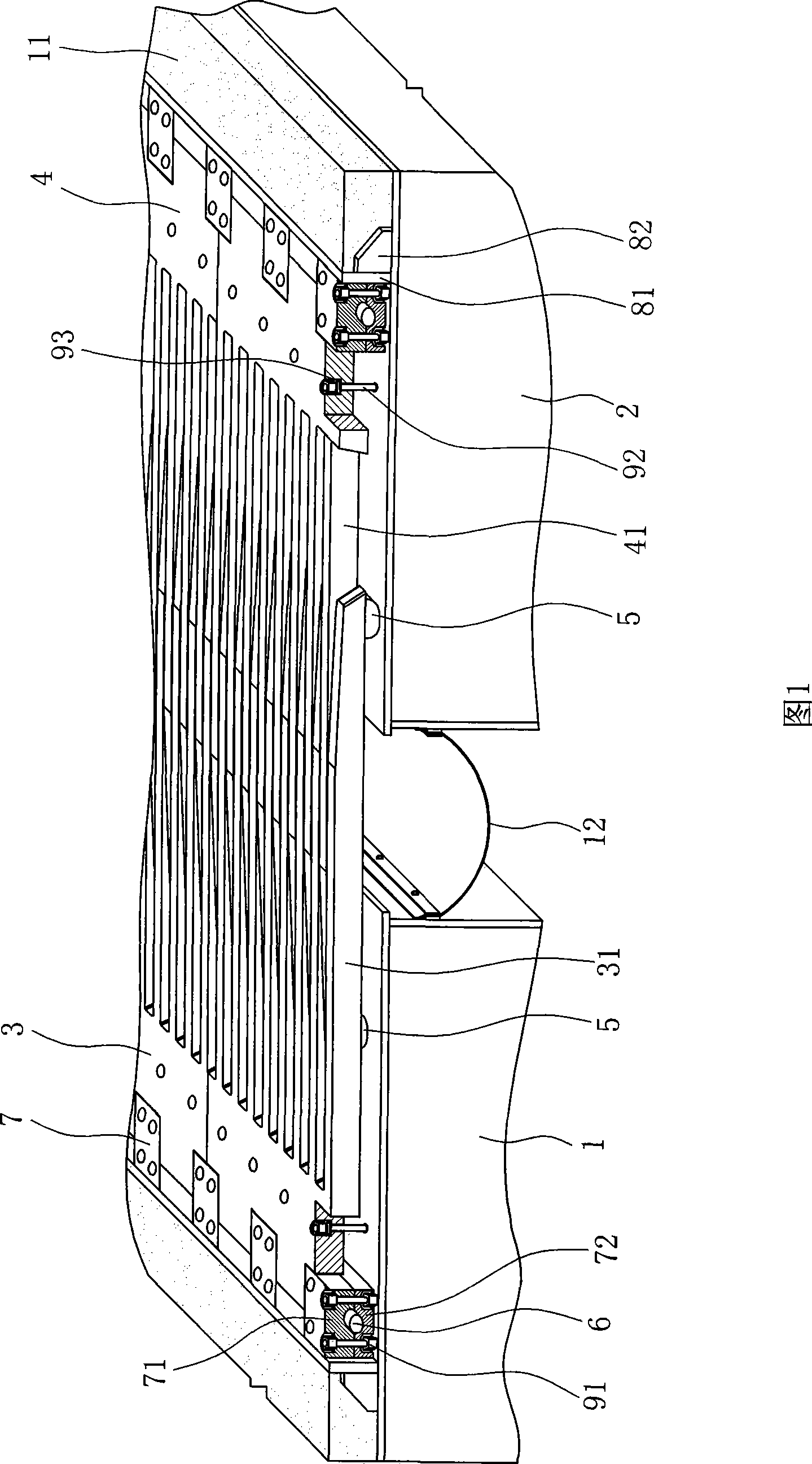
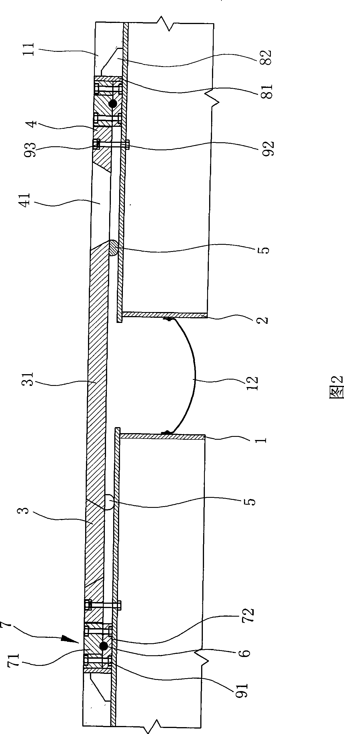
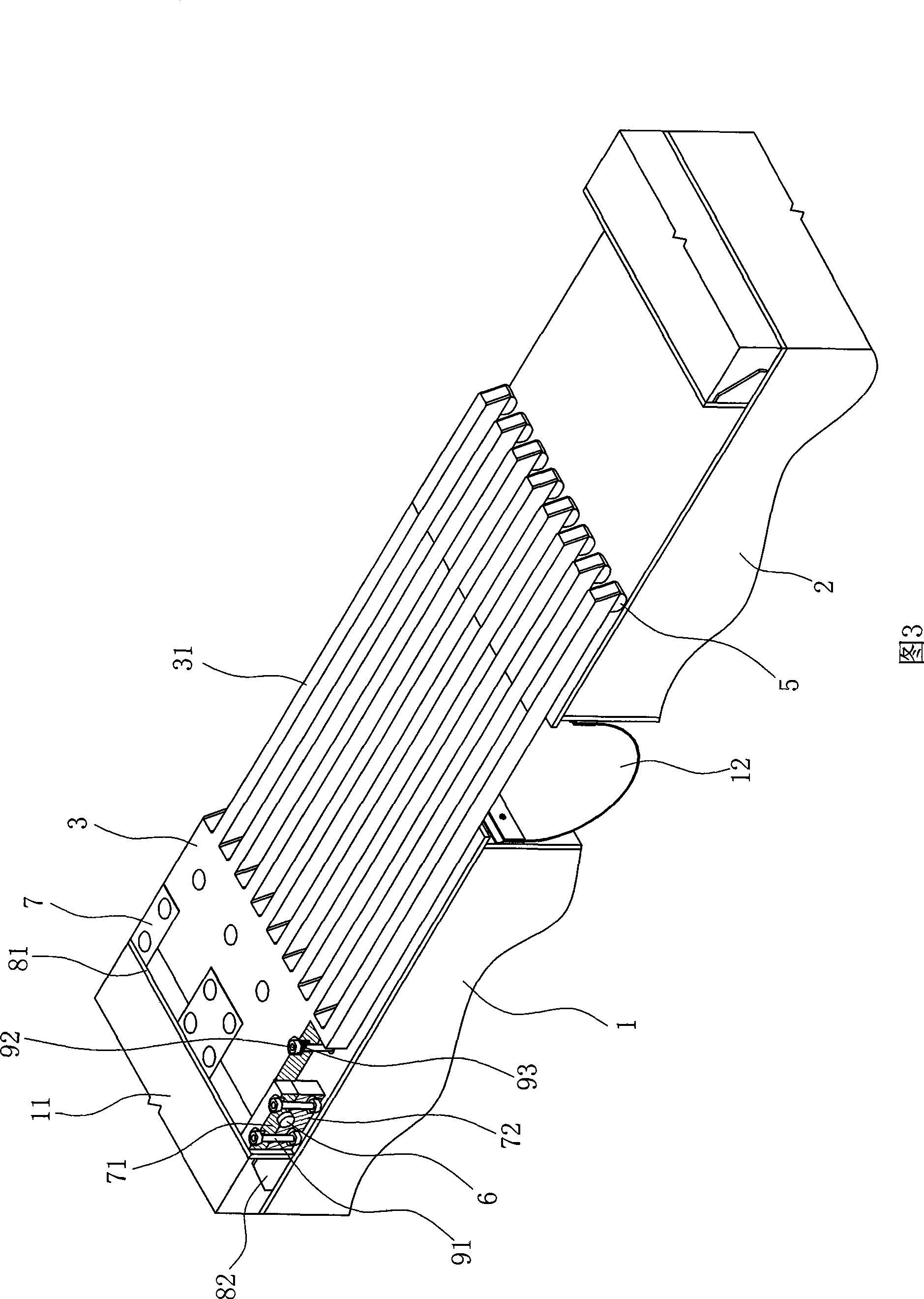
[0021] As shown in Figures 1 to 4, it is an embodiment in which the first and second girder bodies on both sides of the bridge expansion joint use steel box girders. The bridge expansion joint device that resists large vertical rotation angle displacement includes There are the first beam body 1 and the second beam body 2 located on both sides of the bridge expansion joint, the first movable comb plate 3 arranged on the first beam body 1 and the second movable comb plate arranged on the second beam body 2 Movable comb board 4;

[0022] Wherein, the first end of the first movable comb plate 3 is provided with comb teeth 31, and the first end of the second movable comb plate 4 also has comb teeth 41 and each comb tooth 31 of the first movable comb plate 3 interacts with each other. Interspersed intervals are arranged, and the comb teeth 31, 41 ...


PUM


Abstract

The invention discloses a bridge expansion joint device for resisting dislocation of an extra large vertical corner, which comprises a first beam body, a second beam body, and a first movable comb-like plate and a second movable comb-like plate. The ends of the first movable comb-like plate and the second movable comb-like plate are provided with comb teeth which are mutually intersected and arranged at intervals. The comb teeth of the first movable comb-like plate and the second movable comb-like plate span the whole bridge expansion joint. Meanwhile, gaps are reserved between the bottoms of the first movable comb-like plate and the second movable comb-like plate and the beam bodies. A slide block is arranged at the bottom of the end of each comb tooth on the first movable comb-like plate and the second movable comb-like plate, and the roots of the first movable comb-like plate and the second movable comb-like plate are rotatably arranged above corresponding beam bodies. When the two beam bodies have vertical corner dislocation, end warping or sinking due to an external force such as loading, the movable comb-like plate on each beam body can rotate correspondingly to the beam body, and each comb tooth is adjusted correspondingly and smoothly, so that each movable comb-like plate keeps smooth, the whole expansion joint device is prevented from being damaged and ensures smooth and safe passing of each vehicle.

Description

technical field [0001] The invention relates to the field of expansion joints of bridges, in particular to a bridge expansion joint device with an expansion capacity of more than 300 millimeters and anti-large vertical corner displacement. Background technique [0002] Existing bridge expansion joint devices are mostly suitable for beam bodies using steel box girders and concrete beams, or composite bridge projects using concrete beams and concrete beams. However, with the continuous development of bridge construction technology, large-span and ultra-large-span steel box girder suspension cable and cable-stayed composite bridges have been more and more respected, and the existing bridge expansion joint devices can no longer be very good. applied to it. [0003] Among the existing bridge expansion joint devices, the comb-type expansion device with fixed comb and movable comb is a better one, especially for super-large bridge expansion joints with an expansion capacity of mor...

Claims


Application Information

Patent Timeline
IPC IPC(8): E01D19/06
Inventor 徐斌
Owner 徐斌
Learn More