

High power LED light source unit for lighting integrated with heat radiator
A technology for LED lighting and light source units, applied in the field of high-power LED lighting light source units, can solve the problems of light source structure, lightening degree, etc., and achieve the effects of not easy heat accumulation, prolonging service life, and improving heat dissipation efficiency
- Summary
- Abstract
- Description
- Claims
- Application Information
AI Technical Summary
Problems solved by technology
Method used
Image

Examples
Embodiment Construction
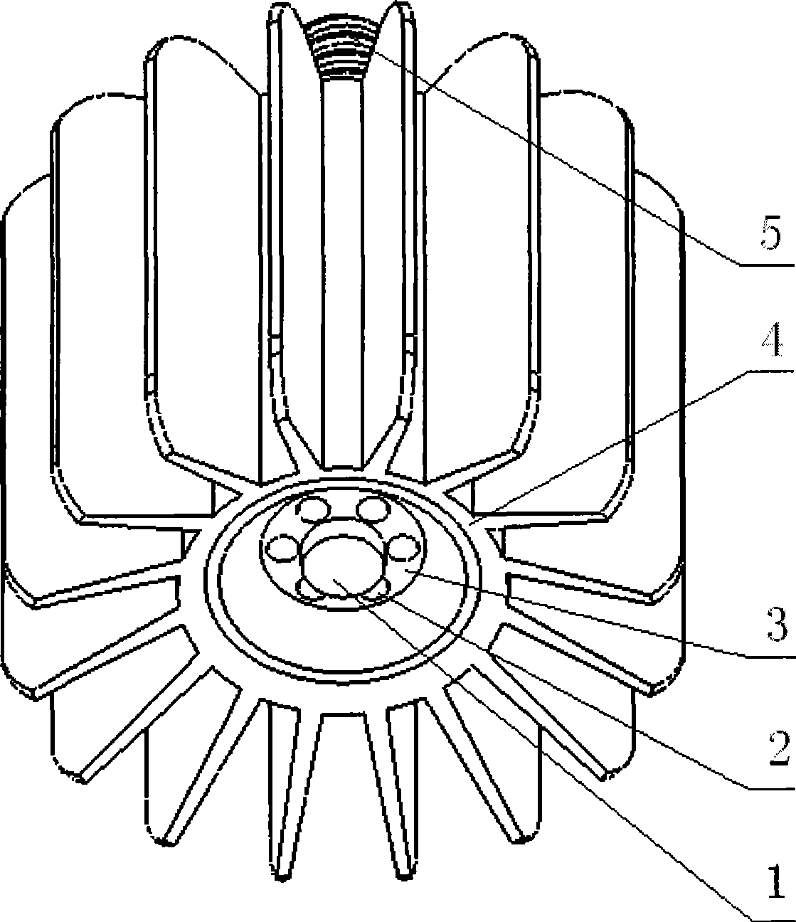
[0021] Embodiments of the present invention will be further described below in conjunction with the accompanying drawings:
[0022] Such as figure 1 As shown, a high-power LED lighting source unit integrated with a radiator includes a cylindrical aluminum radiator 4 with sixteen cooling fins around it, and a high-power LED1, and the positive and negative poles are led out by circuit connection, and at the other end of the radiator 4 corresponding to the LED mounting surface, there is an external thread light source connector that is connected to the positive and negative poles of the LED and can be flexibly connected with the matching internal thread lamp interface 5. On the main body of the heat sink 4 near where the LED is installed, there are six through holes 2 through which both ends pass through along the axial direction of the heat sink 4 .
[0023] It has been proved by tests that the LED lighting fixture of the present utility model really solves the problem, realize...
PUM
 Abstract
Description
Claims
Application Information