
Display apparatus

A display device and display part technology, applied in static indicators, optics, instruments, etc., can solve problems such as the limitation of the application amount of touch panels

Inactive Publication Date: 2009-06-10
JAPAN DISPLAY INC
View PDF3 Cites 28 Cited by
  • Summary
  • Abstract
  • Description
  • Claims
  • Application Information

AI Technical Summary

Problems solved by technology

Therefore, the application amount of the touch panel using the resistive film method is limited

Method used


Image

  • Display apparatus
  • Display apparatus
  • Display apparatus

Examples


Embodiment Construction

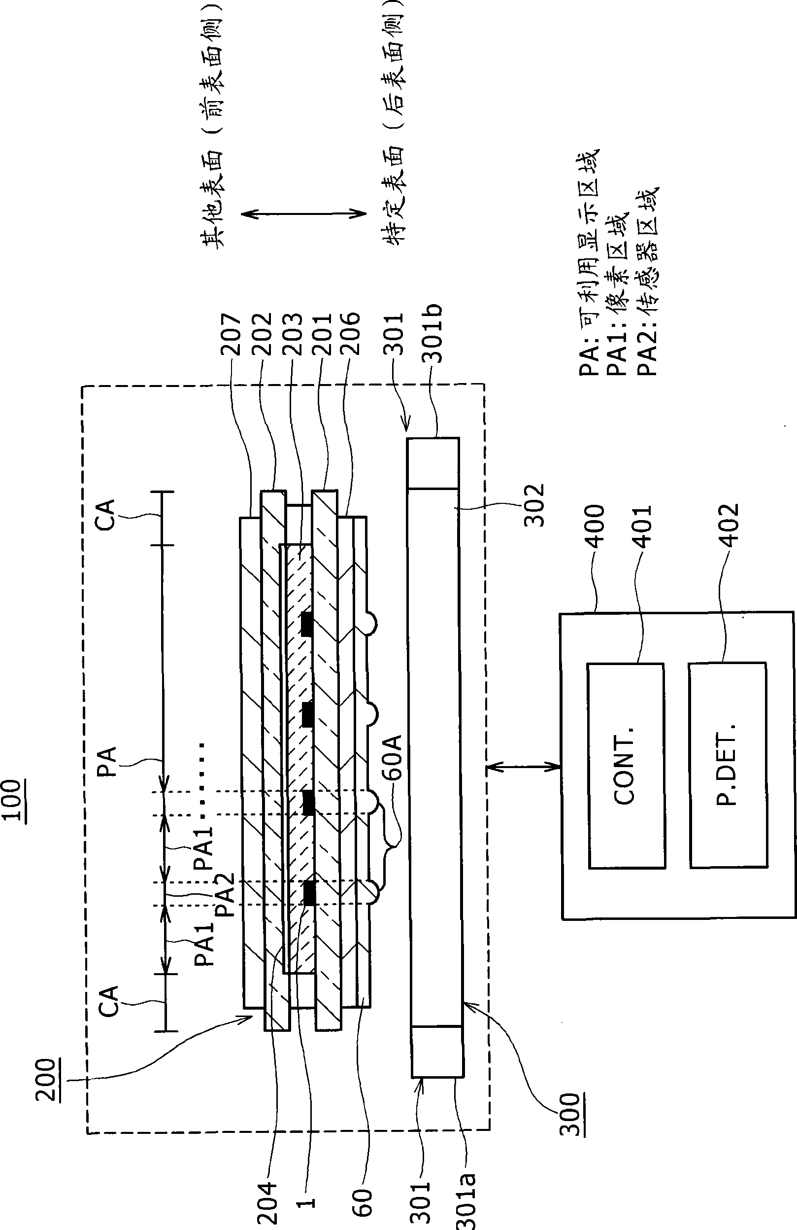
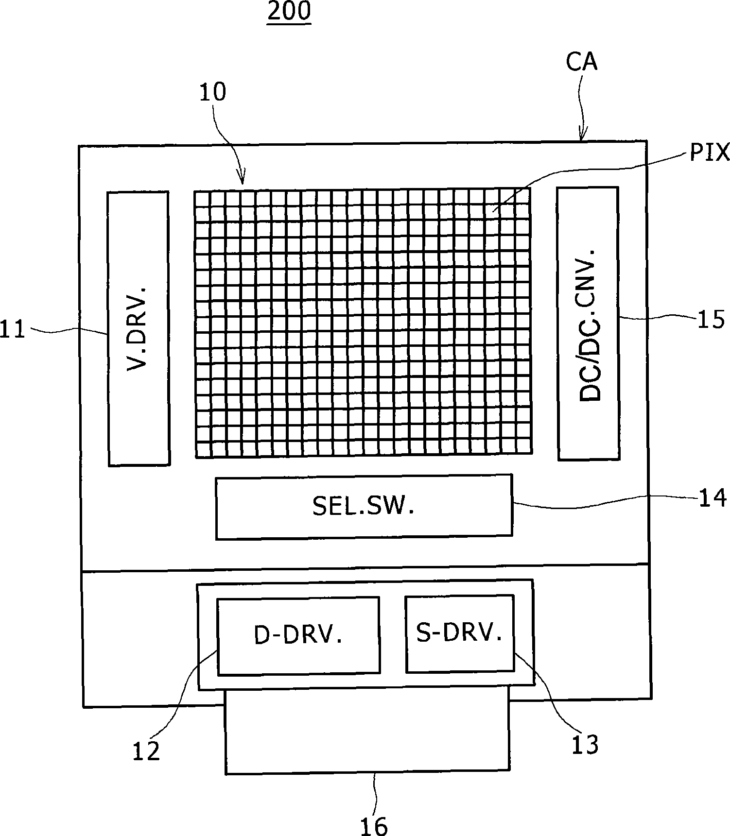
[0064] By referring to the accompanying drawings, the following description explains the embodiments provided by the present invention as embodiments for mainly implementing typical liquid crystal display devices. Embodiments according to the present invention are implemented as a so-called transmissive type liquid crystal display device in which light irradiated to the rear surface of a display portion of the display device is emitted from the front surface of the display portion as display light. The rear surface of the display portion is a surface on the side opposite to the front surface side from which display light is emitted. For such reasons, in the following description, a liquid crystal display device is referred to as a transmissive type liquid crystal display device of a transmissive type.

[0065] overall structure

[0066] figure 1 The cross-sectional view of is schematically showing the cross-section of the overall structure of the transmissive liquid crystal ...


PUM

PropertyMeasurementUnit
band gapaaaaaaaaaa

Abstract

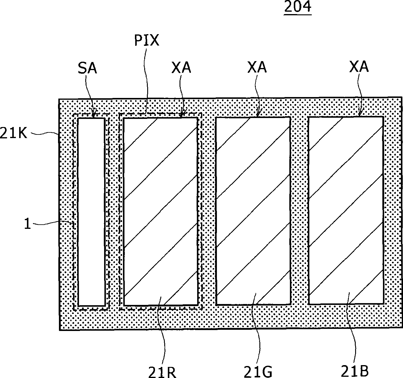
Disclosed herein is a display apparatus including a display section; a light radiating section; a plurality of light converging lenses; and a plurality of light receiving devices, wherein the display section includes pixel areas each used for creating a pixel section, and sensor areas each used for creating one of the light receiving devices; the light radiating section outputs light and radiates the output light to the display section from a particular-side surface of the display section; each of the light converging lenses is created in one of the sensor areas each located in the display section and converges light generated by the light radiating section on a focal point inside the display section, passing on the converged light to the other-side surface of the display section; and each of the light receiving devices is created in one of the sensor areas to serve as a device for receiving light which arrives at the other-side surface of the display section as light reflected by a subject of detection.

Description

technical field [0001] In general, embodiments of the present invention relate to a display device provided with a display section having a pixel area and a sensor area in each of which a pixel section and a light receiving device are respectively provided. Specifically, an embodiment of the present invention relates to a technique for improving utilization efficiency of light reflected by a detection-subject body in contact with or close to a display portion and received by a plurality of the above-mentioned light receiving devices . In the following description, a detection target object is also referred to as a detection target or simply as a detection target. Background technique [0002] A liquid crystal display device, an organic EL (electroluminescence) display device, and a display device using an electrophoretic method are generally known display devices. [0003] Along with the thinning of the display device, it is desired that the display device not only has the...

Claims


Application Information

Patent Timeline
Patent Type & Authority Applications(China)
IPC IPC(8): G02F1/133G06F3/042G06F3/041
CPCG02F2201/58G02F1/133526G02F2001/13312G06F3/0412G06F3/0421G02F1/13312
Inventor 猪野益充杨映保田中勉山口和范樋口胜
Owner JAPAN DISPLAY INC
Learn More