Area light source device and method for making same

A surface light source and light source technology, which is applied in the direction of light source, electric light source, lighting device, etc., can solve the problems of easy cracking due to heat, large area, flammability, etc., so as not to expand and deform, improve low transmittance, and reduce brightness loss Effect

Inactive Publication Date: 2009-06-10
CHIN WEI MIAO IND
View PDF0 Cites 21 Cited by
  • Summary
  • Abstract
  • Description
  • Claims
  • Application Information

AI Technical Summary

Problems solved by technology

[0004] In the current side-illuminated backlight structure, the light guide plate 51 is made of transparent plastic plates such as acrylic, polycarbonate (PC), polymethyl methacrylate (PMMA), but has the following disadvantages: ( 1) poor rigidity, easy to distort when the area is large; (2) easy to be deformed by thermal expansion; (3) easy to crack when heated; and (4) not resistant to high temperature and flammable
The side-illuminated light will have obvious attenuation phenomenon with the distance traveled in the glass, which will cause the loss of luminosity. Therefore, there has been no application of using glass material as a light guide plate so far.

Method used


Image

  • Area light source device and method for making same
  • Area light source device and method for making same
  • Area light source device and method for making same

Examples


Embodiment 1

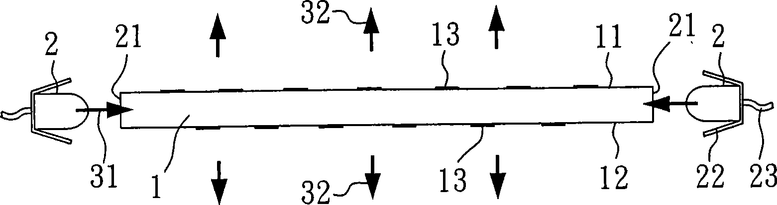
[0053] see image 3 , which is the surface light source device of the first embodiment, including an ultra-clear glass light guide plate 1 and two side-illuminated LED light sources 2 . Wherein, the ultra clear glass light guide plate 1 has a first surface 11 , a second surface 12 opposite to the first surface 11 , and two light incident surfaces 21 perpendicular to the first surface 11 and the second surface 12 . The ultra-clear glass light guide plate 1 has a light guide pattern 13 with white paint dots arranged on the first surface 11 and the second surface 12 . The two side-illuminated LED light sources 2 respectively have a lampshade 22 and a circuit control system 23 , and are arranged on the light incident surface 21 of the glass light guide plate 1 . And emit an incident light 31 into the ultra clear glass light guide plate 1 , and finally emit an outgoing light 32 from the first surface 11 and the second surface 12 .

[0054] In this embodiment, both the first surfa...

Embodiment 2

[0056] see Figure 4 , which is the surface light source device of the second embodiment, like the first embodiment, including an ultra-clear glass light guide plate 1 and two side-illuminated LED light sources 2 . The difference is that in the second embodiment, the first surface 11 has an etched dot pattern 15 , and the second surface 12 has a metal coating layer 14 . After the incident light 31 enters the ultra-clear glass light guide plate 1 from the incident surface 21 , it is reflected by the metal coating layer 14 so that the light only exits from the first surface 11 to increase the light quantity of the outgoing light 32 .

Embodiment 3

[0058] see Figure 5 , which is the surface light source device of the third embodiment, including an ultra-clear glass light guide plate 1 and a side-illuminated LED light source 2 . Wherein, the first surface 11 of the ultra-clear glass light guide plate 1 does not have any pattern, and the second surface 12 has a light guide pattern 13 laid with white paint and a metal coating layer 14 . After the side-illuminated LED light source 2 emits incident light 31 , the incident light 31 enters the ultra-clear glass light guide plate 1 through the incident surface 21 , and then exits from the first surface 11 .


PUM


Abstract

The present invention relates to a method for preparing area light source and the structure thereof. The area light source comprises a high-transparency ultra-white glass light conducting plate with penetration degree higher than 90% and at least one side radiation light source, wherein, the glass light conducting plate is provided with a first surface, a second surface opposite to the first surface, and a light entering surface which is at least perpendicular with the first surface and the second surface. The side radiation light source is configured on the light entering surface of glass light conducting plate and radiates light into the glass light conducting plate. The glass light conducting plate is also provided with a conducting pattern configured on the second surface for radiating the light uniformly through the pattern.

Description

technical field [0001] The invention relates to a surface light source device, in particular to a surface light source device using a high-transparency ultra-clear glass as a light guide plate. Background technique [0002] In order to obtain uniform brightness output of the light source, many light source device designs are developed towards a planar structure. Flat backlights have a wide range of applications, including LCD backlights, flat pattern backlights, flat backlights for lighting, and backlights for indicator lights. All require uniform flat backlights to achieve certain effects. At present, commercial backlights are mainly divided into two types, one is a direct-type backlight, and the other is a side-type backlight. direct-lit backlight, such as figure 1 As shown, it generally includes components such as a cold cathode tube (CCFL, Cold Cathode Fluorescent Lamp) 62 , a diffuser plate 61 , a reflector plate 63 , and a lamp tube fixing seat 64 . The cold cathode...

Claims


Application Information

Patent Timeline
Patent Type & Authority Applications(China)
IPC IPC(8): G02F1/13357G02B6/00G02B1/02H05B37/02G02B1/10
Inventor 叶均懋
Owner CHIN WEI MIAO IND
Why Eureka
Try Eureka