
Method for acquiring wiring path of signal line

A signal line and path technology, applied in the field of obtaining the layout path of signal lines, can solve the problems of time waste, increase the time of signal line layout, increase the difficulty of center point coordinates, etc., and achieve the effect of saving wiring space and improving wiring quality

Inactive Publication Date: 2009-06-10
滨海县迪寄电子科技有限公司
View PDF0 Cites 6 Cited by
  • Summary
  • Abstract
  • Description
  • Claims
  • Application Information

AI Technical Summary

Problems solved by technology

[0004]However, the above method of interspersing the third signal line between the first and second signal lines may not be able to quickly find the exact center due to human factors Point coordinates are used for laying the third signal line, which causes a waste of time; in addition, the laying path of a pair of signal lines is not a single straight line, and there may be at least one turning point where the slope changes. In this way, it will undoubtedly increase The difficulty of finding the coordinates of the center point between the first and second signal lines; moreover, even if the coordinates of the center point between the first and second signal lines are accurately found according to the above method, and the third signal The line is laid between the first and second signal lines, but, because this stage does not consider whether the line spacing between the third signal line and the first and second signal lines exceeds the distance allowed by the line layout rules If so, it will affect the wiring quality of the printed circuit board. It is necessary to find other layout space in the printed circuit board to reconfigure the layout position of the third signal line. In this way, the layout of the signal line will undoubtedly be increased. time

Method used


Image

  • Method for acquiring wiring path of signal line
  • Method for acquiring wiring path of signal line
  • Method for acquiring wiring path of signal line

Examples


Embodiment Construction

[0032] The following is a description of the implementation of the present invention through specific examples, and those skilled in the art can easily understand other advantages and effects of the present invention from the content disclosed in this specification.

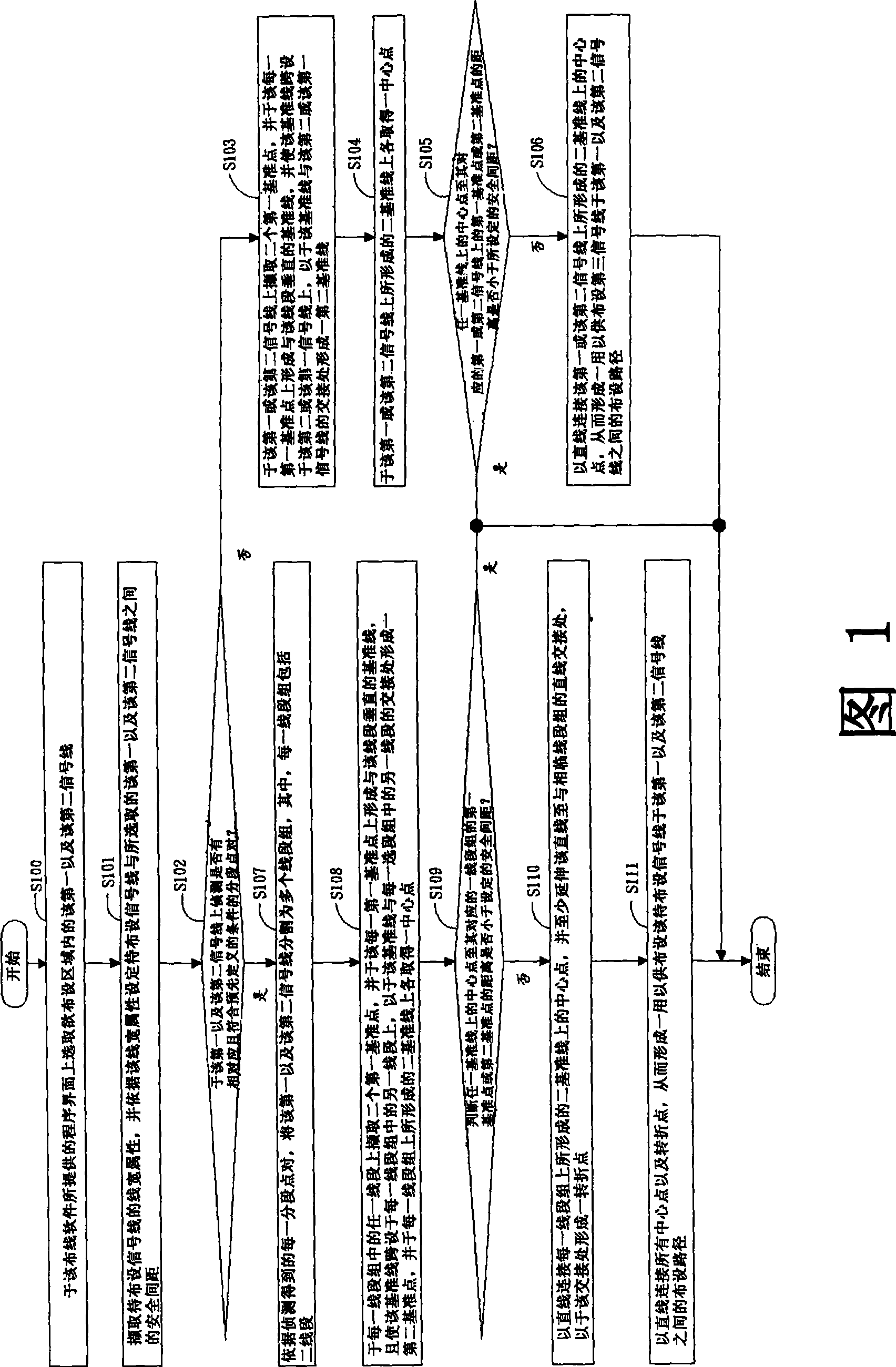
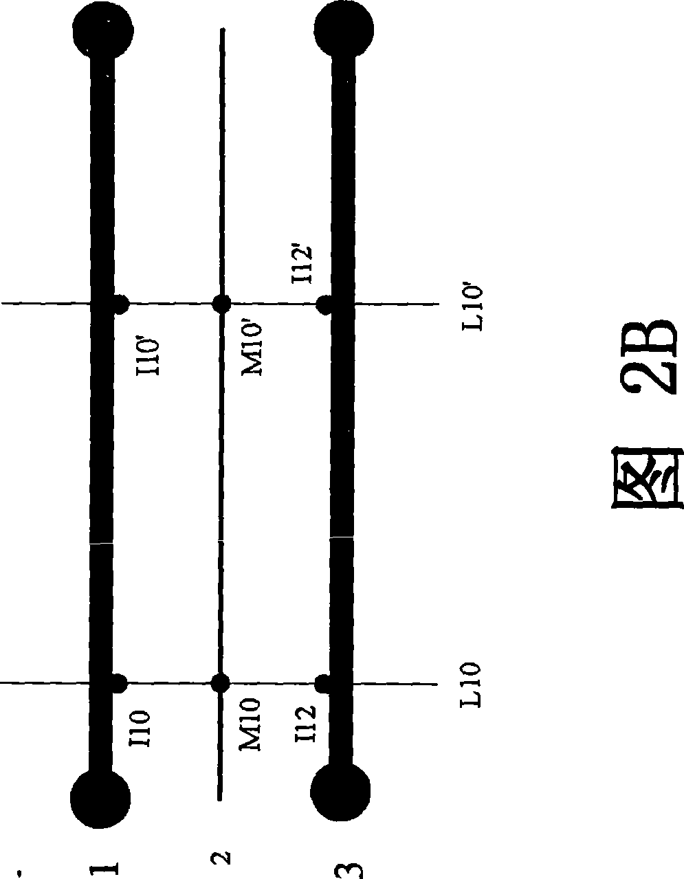
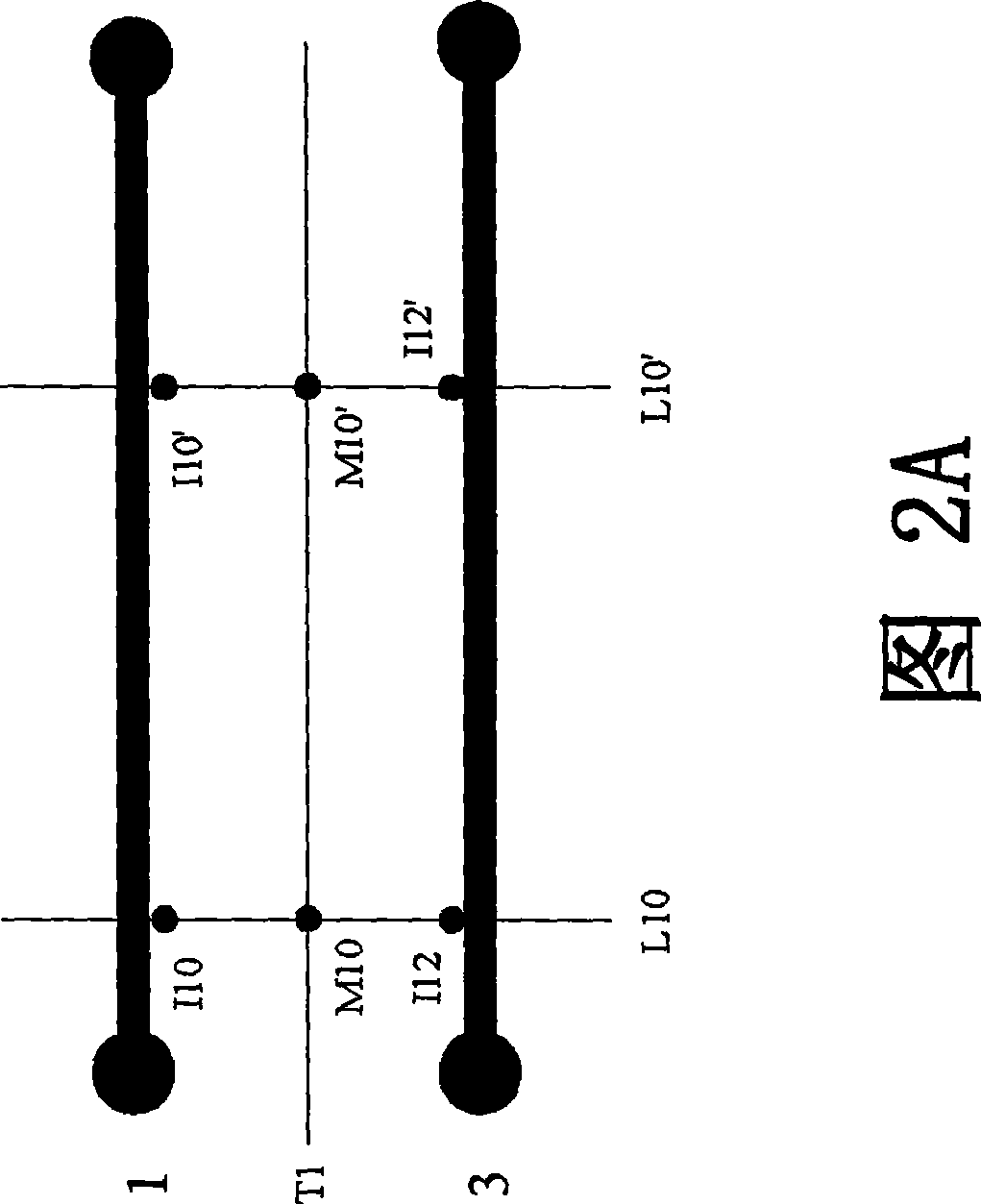
[0033] Please refer to FIG. 1 , which is a schematic diagram showing the operation flow of the method for obtaining the routing path of the signal lines of the present invention. As shown in the figure, the method for obtaining the layout path of the signal line of the present invention is applied to the wiring software of the printed circuit board executed by the data processing device, which can be, for example, a personal computer, a notebook computer, a server or Workstation, etc., and the wiring software can be, for example, Allegro, Protel, etc. In this embodiment, as shown in FIG. 2A (or FIG. 3A ), the printed circuit board has at least one pair of first signal lines 1 (or 1') and second signal lines 3 tha...


PUM


Abstract

The invention discloses a method for acquiring a laying path of signal lines, which is applied to wiring software of a printed circuit board which is provided with a first signal line and a second signal line. The method comprises: forming a reference point on the first signal line and the second signal line respectively, and acquiring a central point on a reference line formed on the first signal line and the second signal line; splitting the first signal line and the second signal line into a plurality of line segment groups after judging that the distance from the central point to the reference point of the first signal line or the second signal line is not less than the preset safe spacing, and selecting two central points corresponding to a clamped area of the two signal lines for each line segment group; using a straight line to connect the central points of various line segment groups, extending the straight line at least to a straight line joint of adjacent line segment groups, and forming a turning point on the joint; and finally using a straight line to connect all the central points and the turning point, and forming the laying path for laying the signal lines to be laid between the first signal line and the second signal line, so as to overcome the prior defects.

Description

technical field [0001] The present invention relates to a signal line laying technology, and more specifically, to a method for obtaining a signal line laying path applied in wiring software of a printed circuit board executed by a data processing device such as a personal computer or a server. Background technique [0002] Usually, the printed circuit board is through the circuit layout (Layout) so that the components on the printed circuit board are electrically connected and generate corresponding functions. At present, wiring engineers usually use such as Allegro, Protel And other wiring software to complete. In addition, with the development of miniaturization of electronic components, the printed circuit boards used to arrange the electronic components are also becoming more and more miniaturized, so that the objects arranged in the printed circuit board (such as electronic components and connecting the various components) The signal line density of electronic compone...

Claims


Application Information

Patent Timeline
Patent Type & Authority Applications(China)
IPC IPC(8): G06F17/50
Inventor 胡锋杨淑敏
Owner 滨海县迪寄电子科技有限公司
Learn More