
Filter sleeve with stirring structure

A technology of filter sleeve and filter sleeve, which is applied in the directions of filtration and separation, moving filter element filter, separation method, etc., can solve the problem that the preservation liquid cannot be effectively driven.

Inactive Publication Date: 2009-06-17
上海蓝盎电子科技发展有限公司
View PDF0 Cites 0 Cited by
  • Summary
  • Abstract
  • Description
  • Claims
  • Application Information

AI Technical Summary

Problems solved by technology

[0002] The stirring function of the filter sleeve barrel is realized by the outer wall, and the existing filter sleeve barrels are all cylinders with smooth outer walls. Therefore, during the stirring process of high-speed rotation, the smooth outer wall cannot effectively drive the preservation liquid, and can only form general vortex

Method used


Image

  • Filter sleeve with stirring structure
  • Filter sleeve with stirring structure

Examples


Embodiment Construction

[0008] Obviously, the solution of the present invention will not be limited only to the embodiment.

[0009] Embodiment is shown in accompanying drawing. For details, please refer to the accompanying drawings.

Description of drawings

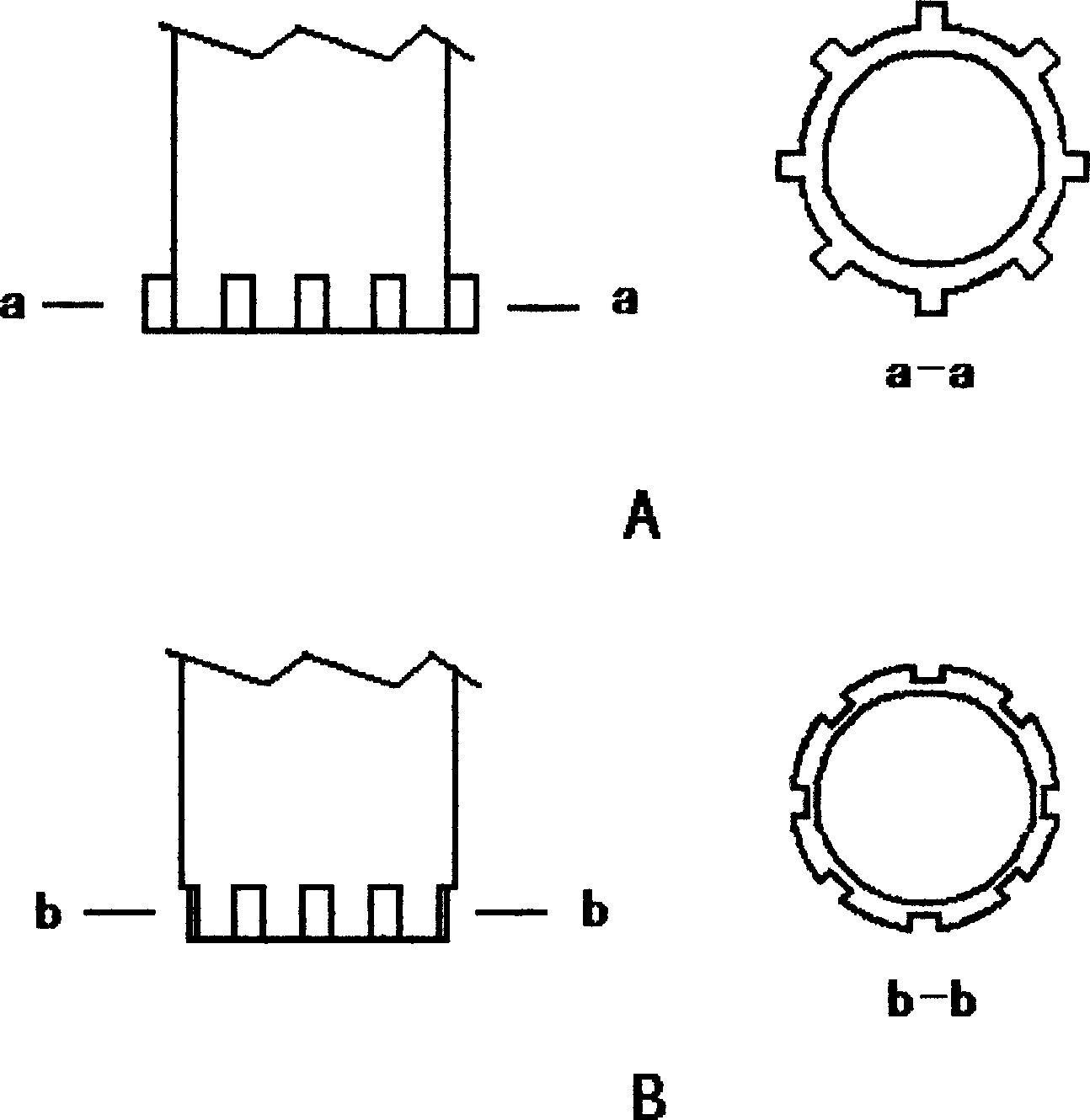
[0010] 1) Accompanying drawing 1 is an embodiment of "adding a raised structure or a groove on the outer wall".

[0011] Scheme A is to add a raised structure on the outer wall, and its cross-section is shown in a-a. The raised structures play a major stirring role. Option B is to add a groove structure on the outer wall, and its cross-section is shown in b-b. Relative to the groove, the outer wall is raised, which plays a major role in stirring.

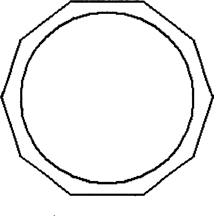
[0012] 2) Accompanying drawing 2 is the embodiment of "changing its cross-sectional shape".

[0013] The outer wall section is polygonal, and the corners and sides of the polygon play a major role in stirring.


PUM


Abstract

The invention relates to a filter sleeve with a stirring structure, which redesigns the shape of the outer wall or the cross section of the filter sleeve, so that the filter sleeve can effectively drive preserving fluid, and the stirring function of the filter sleeve can be improved, namely the filter sleeve is provided with the stirring structure and is a stirrer with strong driving capability and stirring function.

Description

Background technique [0001] Tinpreper-2000, a liquid-based cytology automatic film production equipment produced by Tinpreper TCT Company of the United States, has been clinically used in exfoliative cytology detection. At the same time, many domestic companies have also introduced similar equipment with the same principle. The key consumable used in this type of equipment is a filter sleeve with a filter membrane. In addition to the filtering function, this set of barrels has an important function: when the equipment is working, driven by the corresponding structural components, the filter set barrel rotates at high speed to stir the preservation solution containing exfoliated cells, so that the cells are evenly dispersed and the mucus components are broken. [0002] The stirring function of the filter sleeve barrel is realized by the outer wall, and the existing filter sleeve barrels are all cylinders with smooth outer walls. Therefore, during the stirring process of high-sp...

Claims


Application Information

Patent Timeline
IPC IPC(8): B01D33/06B01D33/067
Inventor 马雪松顾苏兰
Owner 上海蓝盎电子科技发展有限公司
Features
  • Generate Ideas
  • Intellectual Property
  • Life Sciences
  • Materials
  • Tech Scout
  • Unparalleled Data Quality
  • Higher Quality Content
  • 60% Fewer Hallucinations
Learn More