

Exhausting structure of thin-wall injection molding die
An injection molding and mold technology, which is applied to the exhaust structure of the mold and the exhaust structure of the thin-walled injection molding mold, can solve the problems of poor strength and shorten the service life of the mold, so as to ensure product quality, reduce the molding cycle, and solve the problem of Difficulty filling effects
- Summary
- Abstract
- Description
- Claims
- Application Information
AI Technical Summary
Problems solved by technology
Method used
Image

Examples
Embodiment Construction
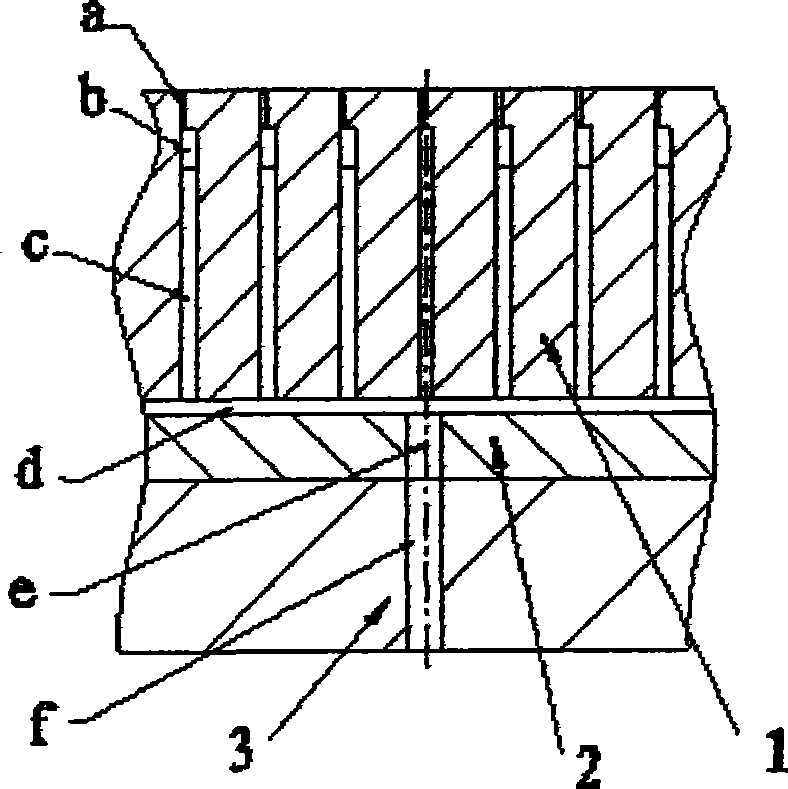
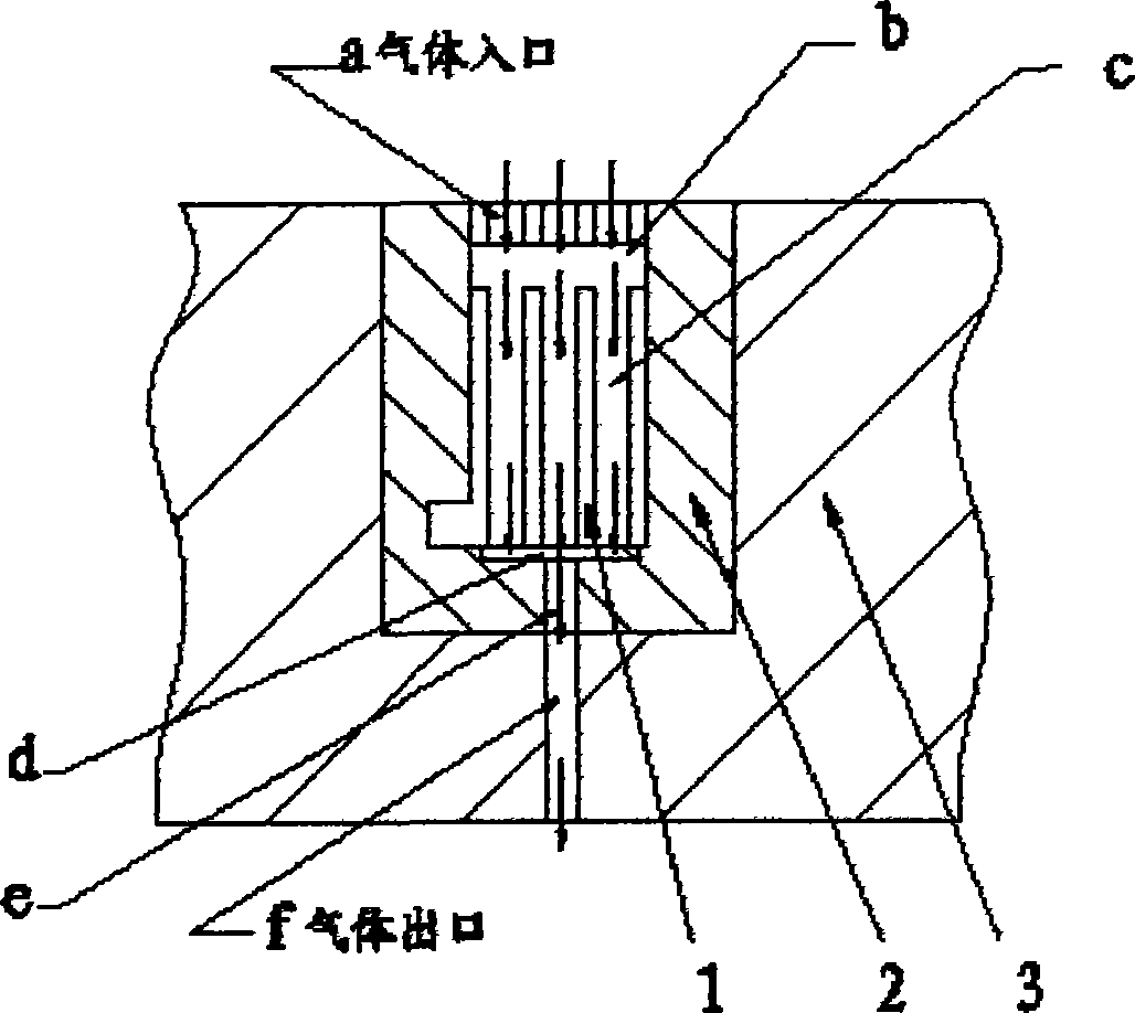
[0010] Preferred embodiment of the present invention, see appendix figure 1 Sectional drawing of the exhaust structure, attached figure 2 A preferred solution for opening exhaust grooves and exhaust slits on the side of the exhaust sheet.
[0011] An exhaust structure for a thin-walled injection molding mold, which is composed of a set of exhaust pieces 1, a base 2 and a mold cavity plate 3. The structure has the following characteristics: a set of exhaust pieces 1 into the base 2 in turn, and then put the assembly into the mold cavity plate 3, the base 2 and the mold cavity plate 3 are connected by screws, and the side of the exhaust piece 1 is provided with a horizontal The exhaust groove b and the longitudinal exhaust groove c are connected to form a T-shaped groove, and a plurality of shallow longitudinal exhaust slits a communicating with it are designed on the upper end of the horizontal exhaust groove b of the exhaust sheet 1. When exhausting, the type The gas in the...
PUM
 Abstract
Description
Claims
Application Information