Method and apparatus for mounting lock on transmission device main body
What is AI technical title?
AI technical title is built by Patsnap AI team. It summarizes the technical point description of the patent document.
A technology of a transmitter and a main body, which is applied in the field of a method and a device for locking the main body of a transmitter, and can solve problems such as large structure and inconvenient operation
Active Publication Date: 2009-06-17
BEIJING RINRONG TECH
View PDF7 Cites 1 Cited by
Summary
Abstract
Description
Claims
Application Information
AI Technical Summary
This helps you quickly interpret patents by identifying the three key elements:
Problems solved by technology
Method used
Benefits of technology
Problems solved by technology
[0002] The locks of the current transmitters are all located on the cover. Due to the relatively large structure of the locks, it is very inconvenient to operate
Method used
Image
Click on the blue label to locate the original text in one second.
Reading with bidirectional positioning of images and text.
Examples
example 1
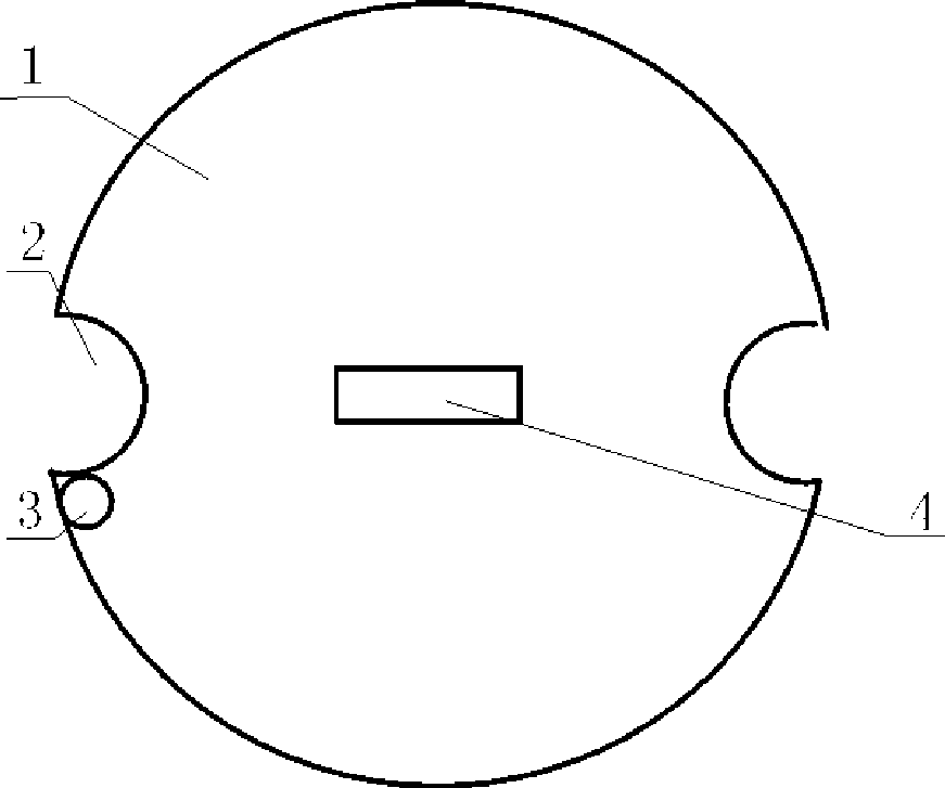
[0021] Such as figure 1 As shown, 1 is the cover of the transmitter, which is cylindrical, 2 is the groove, which is set on the outer edge of the circumference, and 3 is the lock hole, which is used to be inserted by the lock tongue when the cover is turned in place, near the groove , 4 is handle, in order to take away cover body.
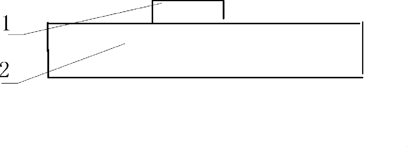
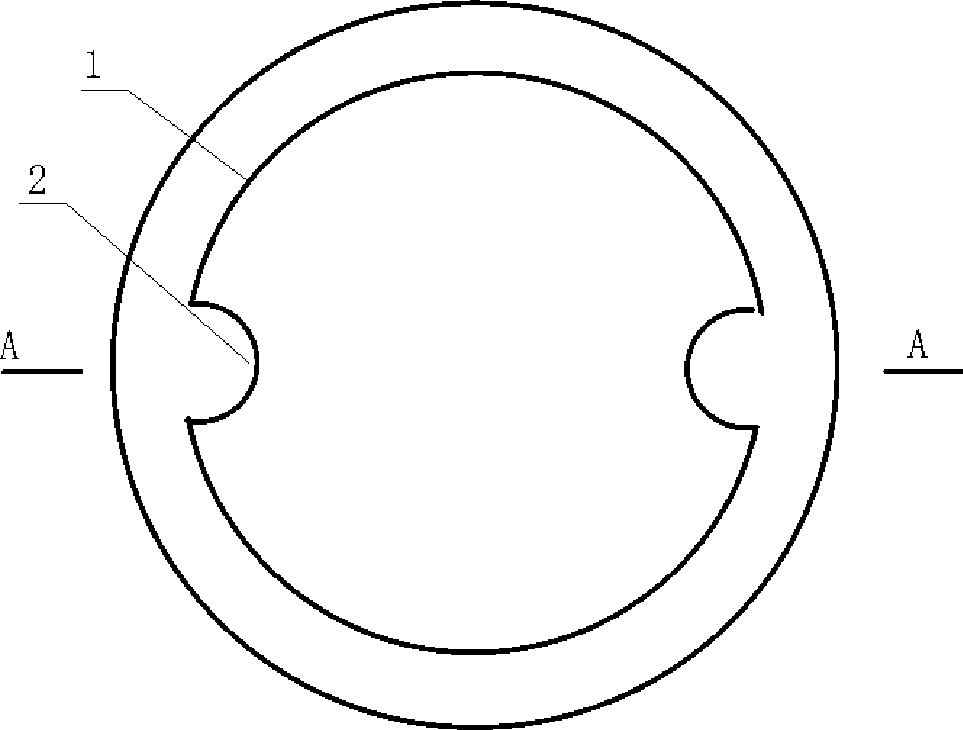
[0022] figure 2 Among them, 1 is the handle and 2 is the cover. image 3 Among them, 2 is the boss, and 1 is the main body of the transmitter.
[0023] Figure 4 Among them, 2 is the groove of boss, and block is installed, and 3 is deadbolt hole, and 4 is lock, and when lock cylinder rotates, deadbolt can be pulled back and released.
[0024] Figure 5 1 is the rotating shaft, which is installed in the groove of the main body of the transmitter, and 4 is the spring, which is installed on the shaft, and is used to ensure that the block blocks the lock in the lock hole when the block is not squeezed by the cover. The lock tongue is not ejected...
example 2
[0027] Such as Image 6 , 2 is the boss of the cover. When the cover is a boss, the main body of the transmitter is an inner groove, and the others are the same as in Example 1.
[0028] Figure 7 Among them, 1 is a dead bolt, 2 and 4 are rotating shafts, 3 is a pull bar, 4 is a rotating disk, 6 is a lock cylinder, and 7 is a lockhole. When the lock cylinder turns, it takes 4 turns, and 3 can move left and right with 1.
PUM
Abstract
The invention discloses a method and a device for mounting a lock on a transmission device body, and relates to the field of pneumatic pipeline transmission. In the prior transmission device, a lock is arranged on a cover; as the lock has a large structure and is quite inconvenient to operate. A lock mechanism is arranged on a transmission device main body; and the lock mechanism is arranged on the sidewall of the transmission main body.
Description
technical field [0001] The invention relates to the field of pneumatic pipeline transmission, in particular to a method and device for locking on the main body of the conveyor. Background technique [0002] The locks of the current transmitters are all located on the cover. Because the structure of the lock is relatively large, it is very inconvenient to operate. [0003] The present invention completely solves this problem. Contents of the invention [0004] The lock mechanism is mounted on the transmitter body. [0005] Preferably [0006] The lock mechanism is mounted on the side wall of the transmitter body. [0007] Preferably [0008] Said device comprises a cover with a groove at least on the peripheral edge for cooperating with an inner boss on the body of the transmitter, interlocking in a groove in its boss, including a stop, mounted on the body of the transmitter In the groove of the inner boss, it is used to block the lock tongue from protruding when the c...
Claims
Application Information
Patent Timeline
Application Date:The date an application was filed.
Publication Date:The date a patent or application was officially published.
First Publication Date:The earliest publication date of a patent with the same application number.
Issue Date:Publication date of the patent grant document.
PCT Entry Date:The Entry date of PCT National Phase.
Estimated Expiry Date:The statutory expiry date of a patent right according to the Patent Law, and it is the longest term of protection that the patent right can achieve without the termination of the patent right due to other reasons(Term extension factor has been taken into account ).
Invalid Date:Actual expiry date is based on effective date or publication date of legal transaction data of invalid patent.

