
Machine-mould integrated tyre vulcanizing device

A technology of tire vulcanization and machine-mold integration, which is applied in the direction of fluid pressure actuation devices, etc., can solve problems such as difficulties in the manufacture of hydraulic cylinder blocks, and achieve the effects of meeting various work needs, simplifying locking devices, and being easy to use

Inactive Publication Date: 2011-05-11
QINGDAO YUANTONG MACHINERY CO LTD
View PDF6 Cites 0 Cited by
  • Summary
  • Abstract
  • Description
  • Claims
  • Application Information

AI Technical Summary

Problems solved by technology

This structure realizes the rotation of the hydraulic cylinder, but since both ends of the piston are equipped with piston rods, and in order to ensure the rotation between the piston rod at one end and the cylinder body, the length of the cylinder body of the hydraulic cylinder must be increased accordingly, resulting in hydraulic pressure Difficulty in making cylinder block

Method used


Image

  • Machine-mould integrated tyre vulcanizing device
  • Machine-mould integrated tyre vulcanizing device
  • Machine-mould integrated tyre vulcanizing device

Examples


Embodiment 1

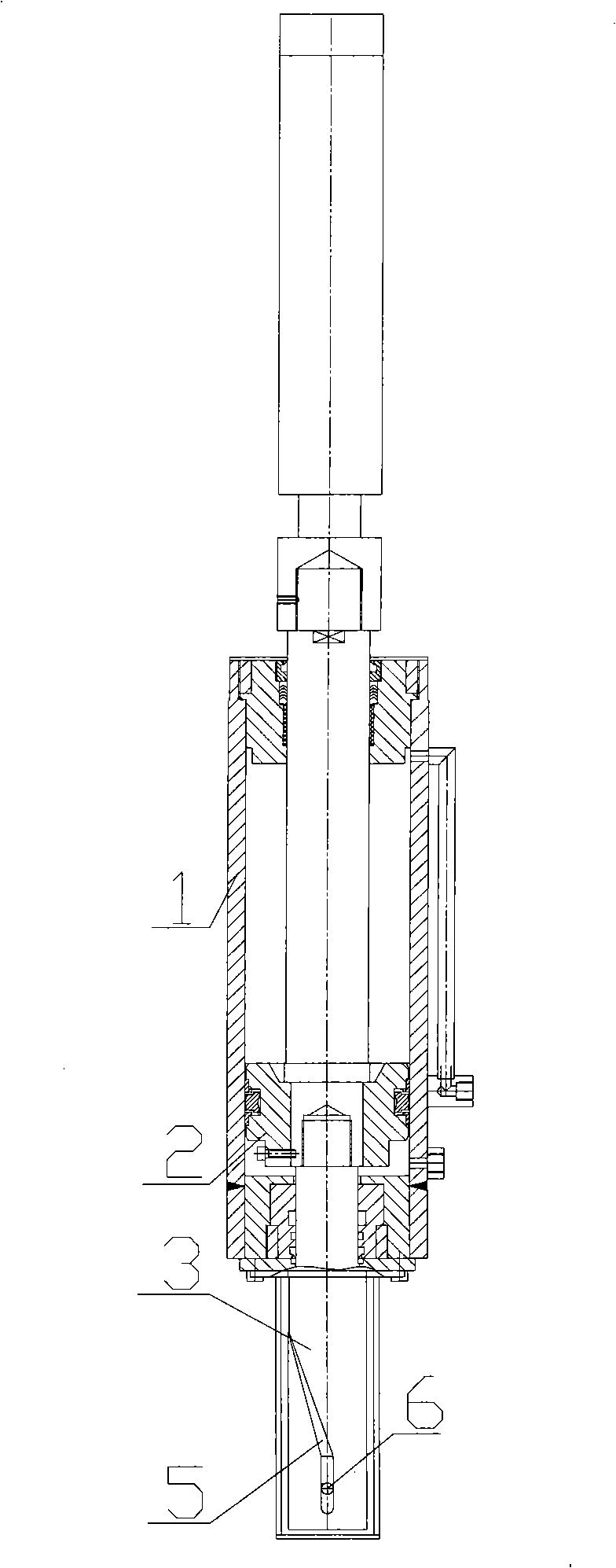
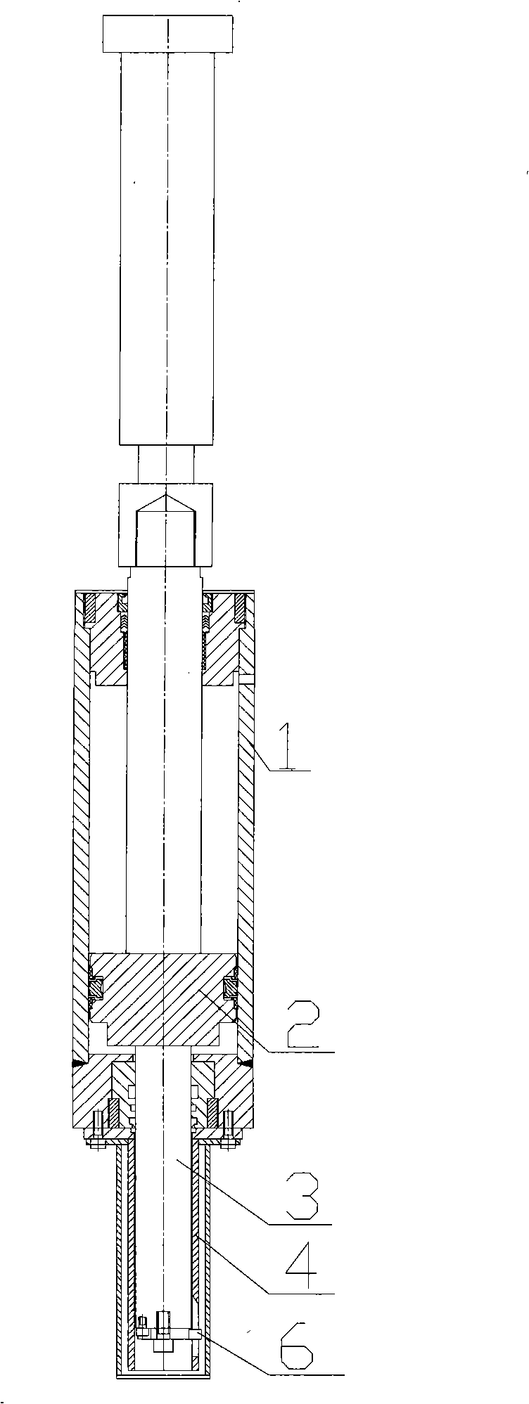
[0015] Such as figure 1 and figure 2 As shown, the hydraulic cylinder includes a cylinder body 1, a piston 2 and a piston rod 3. Piston 2 and piston rod 3 can be made integrally, also can be made separately, and then affixed into one. The two ends of the piston 2 are equipped with piston rods 3, the bottom of the cylinder body 1 is fixedly connected to the piston rod sleeve 4, the piston rod 3 on this side can slide in the piston rod sleeve 4, and the gap between the piston rod 3 and the piston rod sleeve 4 Set the rotation guide device, the structure of the device is shown in the figure, the lower part of the piston rod sleeve 4 is provided with a rotation guide groove 5, and the bottom of the corresponding piston rod 3 is provided with a pin 6, and the pin 6 extends into and is stuck in the rotation guide groove 5 At the same time, the pin 6 can slide along it in the rotation guide groove 5.

[0016] The hydraulic cylinder can be used as a locking device of a mold-integr...

Embodiment 2

[0019] The rotary guiding device in this embodiment is: one or more rotary guiding grooves 5 are set on the outer surface of the lower part of the piston rod 3, one or more pins 6 are set on the inner surface of the corresponding piston rod sleeve 4, and one end of the pin 6 is connected to The piston rod sleeve 4 is fixedly connected, and the other end is stuck in the rotation guide groove 5, and can slide along the guide groove.

[0020] Others are the same as embodiment 1.


PUM


Abstract

The invention relates to a liquid pressure actuating mechanism, in particular to a hydraulic drive device with rotation function and a machine-mold integrated tire vulcanization device employing the hydraulic device. The machine-mold integrated tire vulcanization device comprises a lower bottom plate and a middle die sleeve. Hydraulic cylinders are spacedly arranged along the circumference direction of the bottom outer edge of the lower bottom plate. Open slots are correspondingly arranged along the cylindrical circumference direction of the lower edge of the middle die sleeve. The hydraulic cylinder comprises a cylinder body, a piston and piston rods. The two ends of the piston are both provided with the piston rods; wherein, the bottom part of the cylinder is fixedly connected with the sleeve of the piston rod; the piston rod at one end of the piston can slide in the sleeve of the piston rod; and a rotary guide device is arranged between the piston rod and the sleeve of the piston rod, correspondingly, the piston rod at the other end of the piston is fixedly provided with a locking device at the top end, and the locking device is arranged above the open slots of the middle dire sleeve. The rotary hydraulic cylinder is adopted as the locking device to realize the locking operation during the vulcanization process through a linear movement and a rotation movement, and simplifies the locking device.

Description

technical field [0001] The invention relates to a hydraulic pressure actuator, in particular to a hydraulic driving device with a rotating function and a mold-integrated tire vulcanizing device using the hydraulic driving device. Background technique [0002] The control process of industrial production requires extensive use of hydraulic control systems. The core element of the hydraulic control system is the hydraulic cylinder. A traditional hydraulic cylinder includes a cylinder body, a piston and a piston rod, and the cylinder body is provided with oil inlet and outlet ports. Through the entry and exit of hydraulic oil, the movement of the piston and piston rod is realized, and various control functions are completed through external components. The piston rod in this hydraulic cylinder all moves in a straight line, and the driven external components can only move in a straight line along with it. In practical applications, many external components not only need to ha...

Claims


Application Information

Patent Timeline
Patent Type & Authority Patents(China)
IPC IPC(8): F15B15/20F15B15/00
Inventor 陈长法
Owner QINGDAO YUANTONG MACHINERY CO LTD
Learn More