
Heat transfer tube for evaporator and method of manufacturing same

A technology of heat transfer tubes and evaporators, applied in the field of heat transfer tubes and their manufacture, can solve the problems of heat transfer tube heat exchange capacity limitation, fluid boiling heat transfer coefficient is not high, etc., and achieve the effect of improving boiling heat transfer capacity

Inactive Publication Date: 2009-06-17
苏州新太铜高效管有限公司
View PDF0 Cites 6 Cited by
  • Summary
  • Abstract
  • Description
  • Claims
  • Application Information

AI Technical Summary

Problems solved by technology

[0004] Although the fin structure can enhance the heat transfer capacity of the heat transfer tube, the fluid boiling heat transfer coefficient in the cavity is not high, which still limits the heat transfer capacity of the heat transfer tube

Method used


Image

  • Heat transfer tube for evaporator and method of manufacturing same
  • Heat transfer tube for evaporator and method of manufacturing same
  • Heat transfer tube for evaporator and method of manufacturing same

Examples


Embodiment Construction

[0021] The specific embodiment of the present invention is described below:

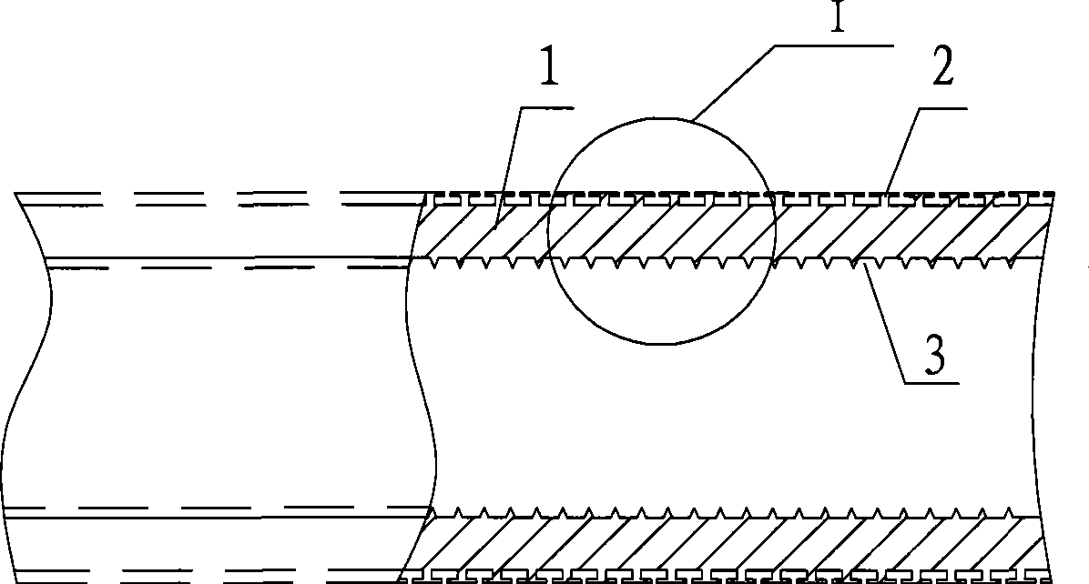
[0022] see figure 1 The shown heat transfer tube for the evaporator includes a tube body 1 with an inner cavity, fins 2 arranged on the outer peripheral surface of the tube body 1 along the axial direction of the tube body 1 and arranged on the inner circumference of the tube body 1 The tooth-shaped grooves 3 are helically distributed along the axial direction of the pipe body 1 on the surface.

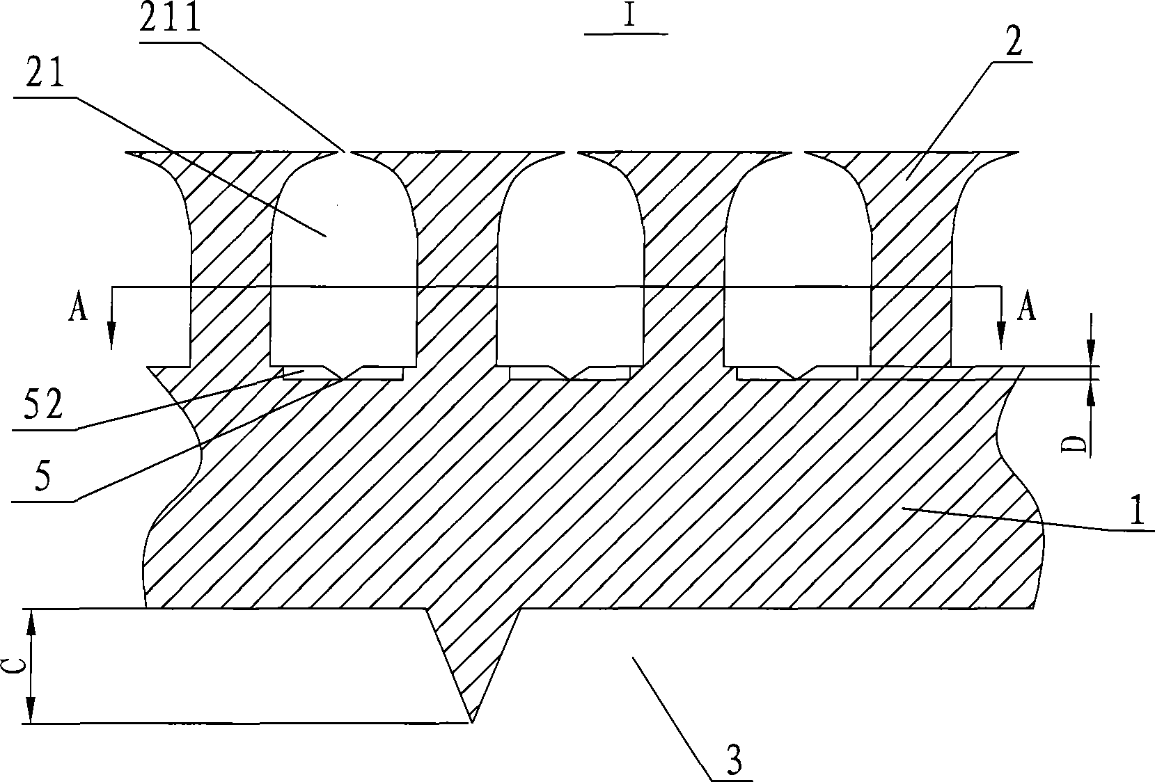
[0023] see image 3 The side walls of the fins 2 are inclined from the bottom to the top of the fins 2 towards the outside of the fins 2, so that a cavity 21 with an opening 211 having a cross-sectional area smaller than the bottom area is formed between adjacent fins 2, and the The openings 211 are also distributed in a helical shape (the helical shape is in the image 3 not shown in ). During the heat exchange process, the bottom surface of the cavity 21 is the part where bubbles form and grow, and the...


PUM

PropertyMeasurementUnit
depthaaaaaaaaaa

Abstract

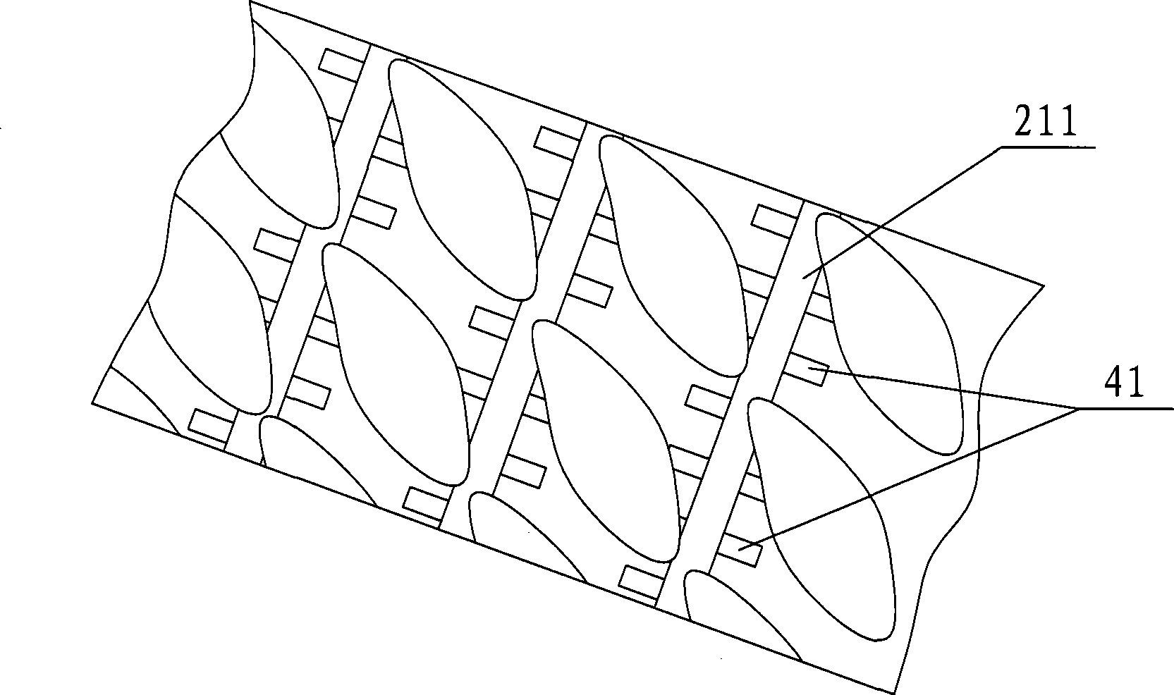
The invention relates to a heat transfer pipe for an evaporator and a production method thereof. The heat transfer pipe is provided with a pipe body with an inner cavity, and fins arranged on the peripheral surface outside the pipe body and spirally distributed along the axial direction of the pipe body. Lateral walls of the fins incline from the bottoms of the fins towards the outside of the tops facing the fins. Empty cavities, the opening sections of which are less than the bottom areas, are formed between adjacent fins; and the bottom surface of each empty cavity is also provided with a first groove and a second groove crossed with the first groove, at least either the first groove or the second groove comprise a plurality of grooves, and the first groove and the second groove have a plurality of crossing nodes. The first grooves, the second grooves and the nodes of the first and the second grooves have worse moisturizing property than the bottoms of the empty cavities so that activation energy or superheat degree of foam generation and growth can be reduced, more gasification core points can be formed, and more foams can be formed so as to improve boiling heat exchange capability. The pipe-outside boiling heat exchange efficiency of the heat transfer pipe is higher than a conventional heat transfer pipe with smooth empty cavity bottom by 7-12 percent.

Description

technical field [0001] The invention relates to a heat transfer tube for an evaporator and a manufacturing method thereof. Background technique [0002] Heat transfer tubes are often used in evaporators, such as flooded evaporators in chillers in central air conditioning systems. The heat transfer tube includes a tube body with an inner cavity, fins formed on the outer wall of the tube body that are helically distributed along the tube body axis, and grooves formed on the tube inner wall that are helically distributed along the tube body axis. In the process of processing, the top of the fin is evenly distributed along the spiral direction of the fin, and a boss is formed between adjacent cuts on the same fin, and the boss is mechanically rolled so that the boss extends to both sides of the fin to achieve The degree of mutual contact with the adjacent fins finally forms a cavity with a small upper opening and a large space below (the bottom surface of the cavity is the oute...

Claims


Application Information

Patent Timeline
Patent Type & Authority Applications(China)
IPC IPC(8): F28F1/42B23P15/00
Inventor 杨伟王进强陈焕倬苏春龙
Owner 苏州新太铜高效管有限公司
Learn More