Polygon arranged central tube type optical fiber ribbon cable

A central tube-type, ribbon-shaped optical cable technology, applied in the direction of fiber mechanical structure, etc., can solve the problems of large signal attenuation and lower performance of optical cables, and achieve the effects of reducing signal attenuation, uniform force, and improving performance

Inactive Publication Date: 2009-06-17
JIANGSU ETERN
View PDF0 Cites 6 Cited by
  • Summary
  • Abstract
  • Description
  • Claims
  • Application Information

AI Technical Summary

Problems solved by technology

[0002] In the prior art, the central tube type ribbon cable includes an optical fiber ribbon set in the center, a loose tube covering the optical fiber ribbon set, fiber paste is filled between the loose tube and the optical fiber ribbon set, and the loose tube is wrapped Covered with a water-blocking tape, the water-blocking tape is covered with a steel-plastic composite tape, and the steel-plastic composite tape is covered with an outer sheath. The optical fiber ribbon group is composed of several optical fiber ribbons. Each optical fiber ribbon is composed of the same The optical fibers are combined side by side, and the optical fiber ribbon group can be covered in the loose tube after being twisted. Therefore, the cross section of the optical fiber ribbon group in the loose tube is rectangular. In this way, the optical fiber at the corner position is due to twist Due to the influence of force bending, close distance from the pipe wall and other factors, the signal attenuation is relatively large, which greatly reduces the performance of the optical cable

Method used


Image

  • Polygon arranged central tube type optical fiber ribbon cable

Examples


Embodiment

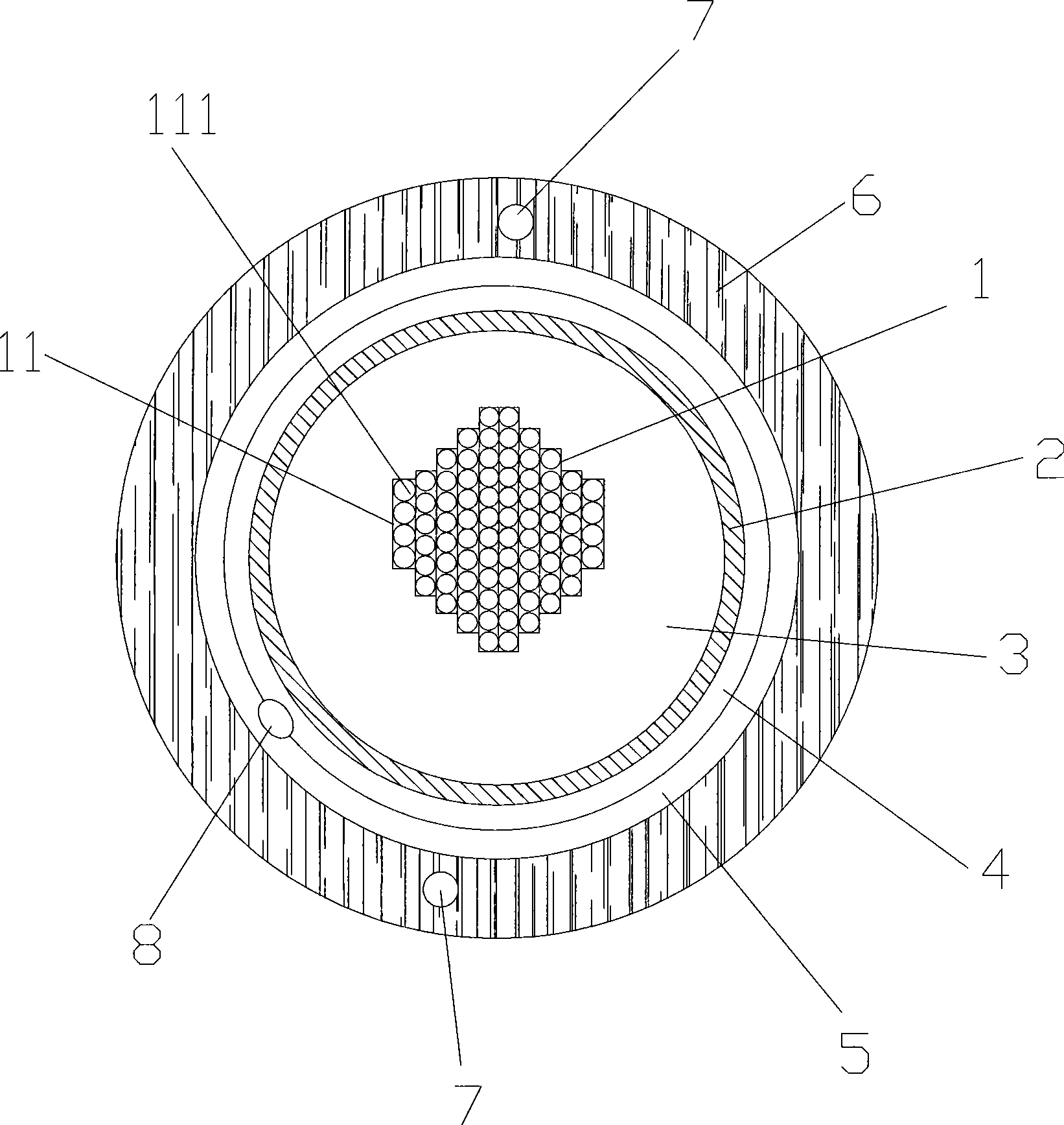
[0012] Embodiment: A central tube-shaped ribbon cable arranged in a polygonal shape, including an optical fiber ribbon group 1 located in the center, a loose tube 2 wrapped outside the optical fiber ribbon group 1, and the space between the loose tube 2 and the optical fiber ribbon group 1 is filled There is fiber paste 3, a tear rope 8 is embedded outside the loose tube 2, the loose tube 2 is covered with a water blocking tape 4, the water blocking tape 4 is covered with a steel-plastic composite tape 5, and the steel-plastic composite tape 5 is outside Covered with an outer sheath 6, embedded in the outer sheath 6 is a reinforcing steel wire 7, the optical fiber ribbon group 1 is formed by stacking several optical fiber ribbons 11, and each optical fiber ribbon 11 is formed by combining several optical fibers 111 side by side;

[0013] The number of optical fibers 111 in each layer of optical fiber ribbon 11 gradually decreases from the inside to the outside, the optical fibe...


PUM


Abstract

The invention discloses a central tube strip optical cable in a polygon arrangement, comprising a fiber ribbon group in the center and a loose tube which wraps the fiber ribbon group; the fiber ribbon group is formed by the superposition of a plurality of fiber ribbons and every fiber ribbon is formed by parallel combination of a plurality of fibers; the number of the fibers of every fiber ribbon decreases gradually from the inside to the outside; the fiber ribbon which is positioned on the inner layer and has the largest number of fibers has at least two layers; the number of the fiber of the fiber ribbon which is positioned in the outer layer and has the smallest number of fibers is two; after superposition of fiber ribbons, the section of the fiber ribbon group is a polygon. In the optical cable, the fibers at the edge or the corner are stressed uniformly and the distance from the tube wall is widened, thereby reducing signal weakening and improving service performance.

Description

technical field [0001] The invention relates to a central tube type ribbon optical cable arranged in a polygonal shape. Background technique [0002] In the prior art, the central tube type ribbon cable includes an optical fiber ribbon set in the center, a loose tube covering the optical fiber ribbon set, fiber paste is filled between the loose tube and the optical fiber ribbon set, and the loose tube is wrapped Covered with a water-blocking tape, the water-blocking tape is covered with a steel-plastic composite tape, and the steel-plastic composite tape is covered with an outer sheath. The optical fiber ribbon group is composed of several optical fiber ribbons. Each optical fiber ribbon is composed of the same number The optical fibers are combined side by side, and the optical fiber ribbon group can be covered in the loose tube after being twisted. Therefore, the cross section of the optical fiber ribbon group in the loose tube is rectangular. In this way, the optical fibe...

Claims


Application Information

Patent Timeline
Patent Type & Authority Applications(China)
IPC IPC(8): G02B6/44
Inventor 邱伟丰陈晓红
Owner JIANGSU ETERN
Why Eureka
Try Eureka