Energy conduction chain

A technology of energy guiding and chain links, which is applied in the field of energy guiding chains, can solve problems such as discontinuous movement and lateral displacement of upper branches, and achieve the effect of reducing noise and reliable guidance

Active Publication Date: 2009-06-17
IGUS
View PDF1 Cites 3 Cited by
  • Summary
  • Abstract
  • Description
  • Claims
  • Application Information

AI Technical Summary

Problems solved by technology

If in the case of a long energy-directing chain, the chain links carrying the rollers are evenly distributed, for example, under the condition of a 50m long chain, when one such chain link is 1m respectively, the upper branch is lifted at the same time would require considerable force, and these would require a strong transmission, resulting in discontinuous motion and possibly undesired lateral displacement of the upper branch

Method used


Image

  • Energy conduction chain
  • Energy conduction chain
  • Energy conduction chain

Examples


Embodiment Construction

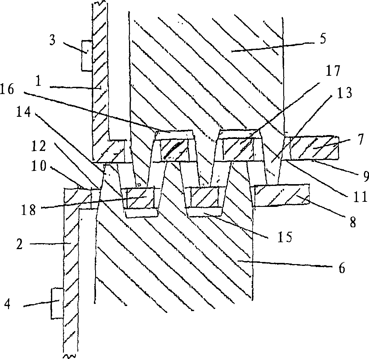
[0022] figure 1 A partial sectional view showing opposite parts of the side straps 1 of the upper branch and the side straps 2 of the lower branch of an energy guiding chain. The pins 3 and 4 are arranged for fastening to the transverse slats not shown in the figure, they are directed towards the inside of the chain link formed by the side straps and the transverse slats, and are placed on their far ends ( shown in the figure) side straps. Rollers 5 , 6 are arranged on the sides of the side webs facing away from the pins 3 , 4 , which are rotatable about a (not shown) horizontal axis in a known manner. These rollers have guide grooves 15 , 16 on their circumference, which are formed on both sides by comb-shaped bodies 13 , 14 . Furthermore, the side webs have extensions 7 , 8 on opposite edges. The opposite surface of the extension serves as the rolling surface 9 , 10 required for the rolling of the rollers 5 , 6 . Longitudinal slots 11 , 12 are provided on these extension...


PUM


Abstract

On an energy guiding chain for guiding hoses, cables and the like, where the upper strand rests on the lower strand and rollers ( 5, 6 ) are provided on at least some chain links of the upper strand and / or the lower strand, which can roll on running surfaces ( 9, 10 ) provided on the chain links of the opposite strand and which, on their running surface, display a number of spaced peripheral guide grooves that can be engaged by the crests ( 13, 14 ) of the rollers of the opposite strand, it is envisaged, in order to facilitate traversing of the chain, that the running surfaces display spaced longitudinal slits that allow the crests of the roller profile to pass through, where the webs ( 17, 18 ) between the longitudinal slits cover the guide grooves on the side facing the other strand, such that the crests of the rollers of the other strand can roll on the webs.

Description

technical field [0001] The invention relates to an energy guiding chain according to the preambles of the independent claims. Background technique [0002] Such an energy guiding chain is described, for example, in the international application WO 99 / 57457. The energy guiding chain disclosed here is equipped with rollers on its side straps, the running surfaces of which have a plurality of spaced, circumferential guide grooves, preferably with a trapezoidal cross-section. The combs next to the guide grooves of the rollers of the opposite branches can engage in the above-mentioned guide grooves, so that the longitudinal guidance can be achieved with the simultaneous offset of the upper branch relative to the lower branch along the transverse direction. [0003] According to the above-described embodiment, the rollers not only roll, but also the tooth surfaces of the intermeshing comb-shaped bodies slide against each other. This leads to increased friction, in particular due...

Claims


Application Information

Patent Timeline
IPC IPC(8): F16G13/16
CPCH02G11/00H02G11/006F16G13/16F16G13/12
Inventor G·布拉泽
Owner IGUS
Why Eureka
Try Eureka