Network protection switching mechanisms and methods of network protection

A technology of network protection and switching devices, applied in electrical components, optical multiplexing systems, multiplexing communications, etc.

Active Publication Date: 2009-06-17
POLATIS
View PDF3 Cites 11 Cited by
  • Summary
  • Abstract
  • Description
  • Claims
  • Application Information

AI Technical Summary

Problems solved by technology

The reasoning behind this is that a maintenance team can be dispatched immediately aft

Method used


Image

  • Network protection switching mechanisms and methods of network protection
  • Network protection switching mechanisms and methods of network protection
  • Network protection switching mechanisms and methods of network protection

Examples


Embodiment Construction

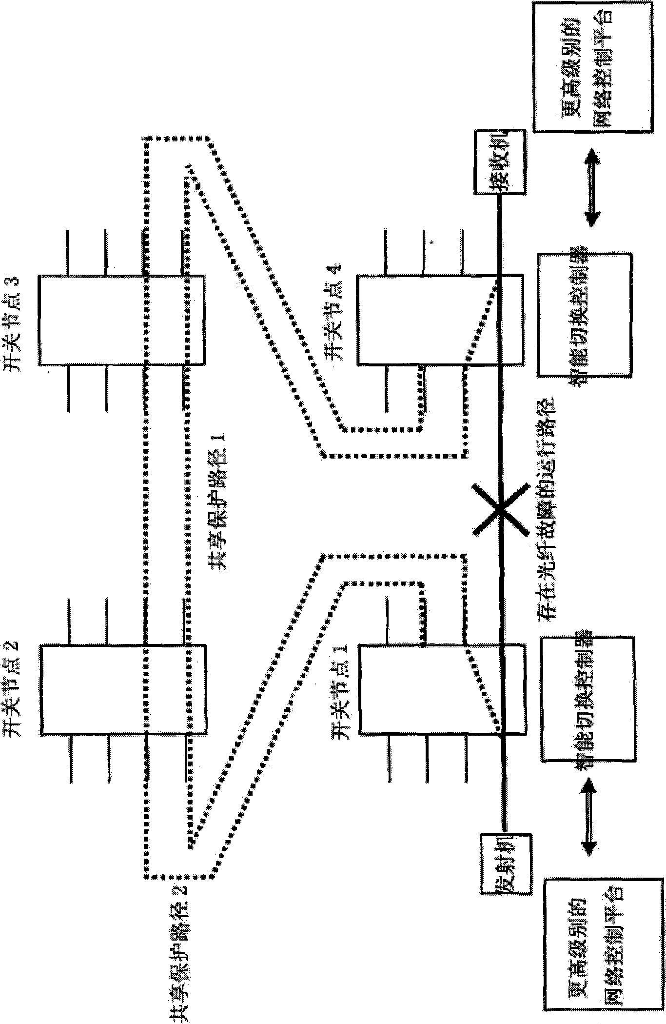
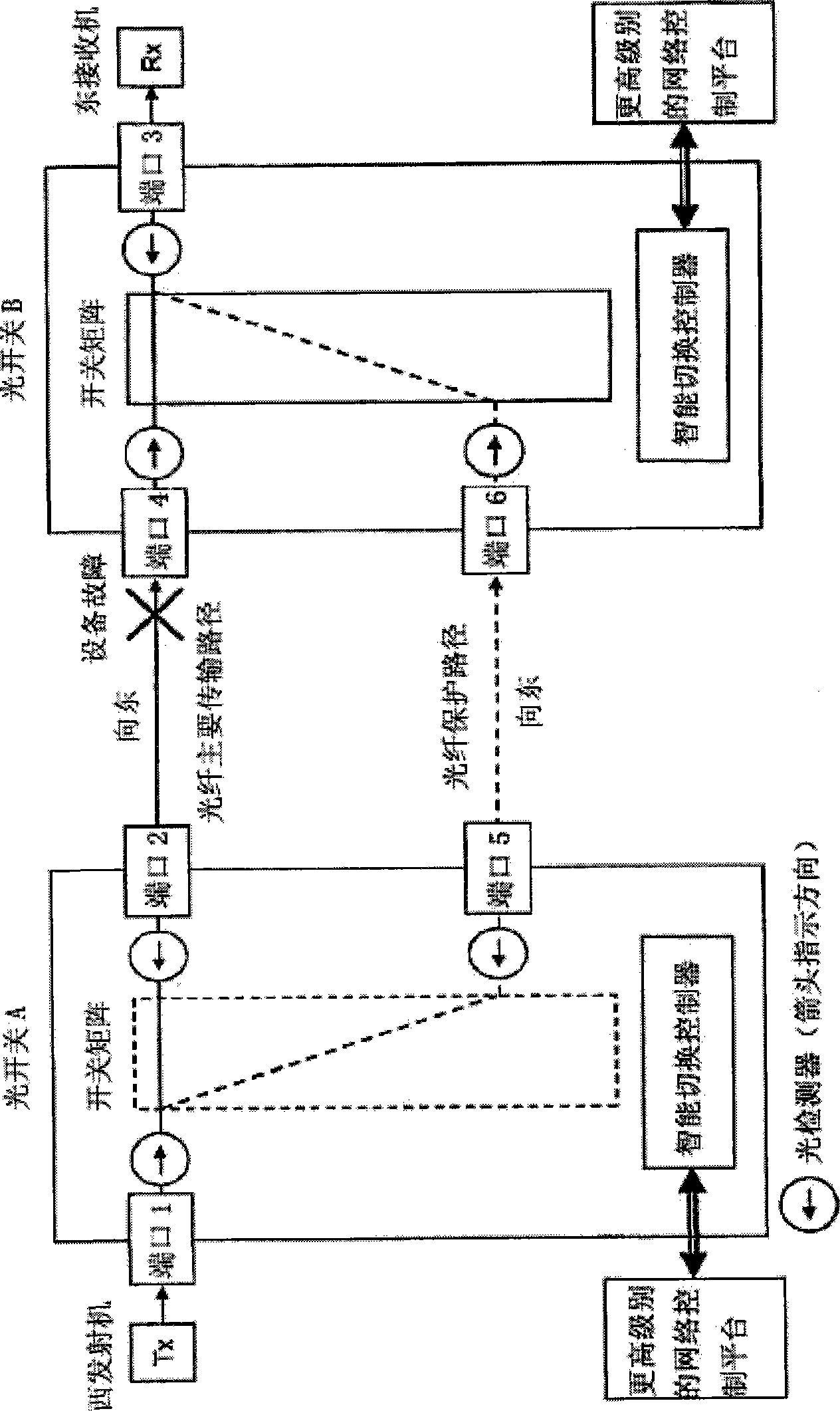
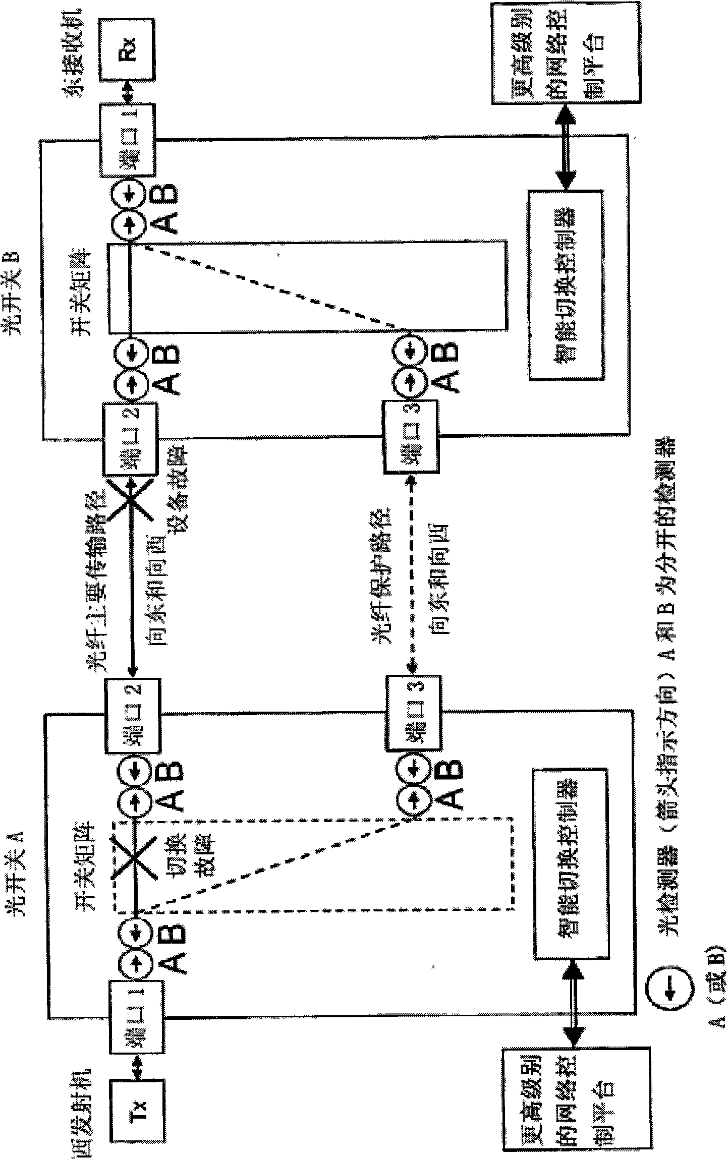
[0044] The embodiment of the present invention improves the speed of fault detection and network protection switching, and the fault can be detected locally in the optical fiber line through the intelligent optical switch with an optical power detector. The switch controller operates without the need for physical layer switching of optical communication results from switch to switch, and without complex and expensive frameworks as required in the prior art. Embodiments can also improve fiber utilization by allowing running lines to share a pool of protection paths.

[0045] The concept of a "shared pool" can be extended to the difficult task of protecting a network against multiple fiber outages, simply by means of detectors, such as optical power detectors, that are monitored in the same way as operational paths after the protected path is prepared. This enables the protection path for bearer transport to be protected by a shared pool of remaining resources. If the network e...


PUM


Abstract

A network protection switching mechanism comprises a plurality of optical switches located at a plurality of nodes; a plurality of optical communication paths between said switches; switch based fault detectors located as part of at least two switches which generate detection results representative of the identification of a fault; switch based controllers located as part of said at least two switches; and internal switch- communication means between said fault detectors and said controllers which facilitate the transmission of detection results from said fault detectors to said controllers; wherein said controllers directly cause switching to an alternative optical communication path dependent upon the receipt of said detection results; whereby autonomous switch based protection without dependence on either inter-switch control communication or higher level network control communication is achieved.

Description

technical field [0001] The invention relates to a network protection switching device and a network protection method. Background technique [0002] Fiber breaks, equipment failures and degradations cause a lot of outages and disconnections. As businesses and consumers become less tolerant of network failures, downtime can be very costly for operators due to damaged revenue and image. As a result, operators are constantly looking for better ways to protect the network from such fiber failures and to use protection bandwidth more efficiently to reduce costs. [0003] Existing protection switching systems usually involve higher level communication or signaling between nodes in the network using complex overhead channel or packet communication. [0004] Designing networks so that they automatically protect against multiple worst-case fiber outages is difficult and expensive. As a result, many network protection solutions typically only provide automatic protection against si...

Claims


Application Information

Patent Timeline
IPC IPC(8): H04J14/00
Inventor 大卫·欧文·刘易斯理查德·安德鲁·詹森
Owner POLATIS
Why Eureka
Try Eureka