Forehead sensor, bandage and forehead sensor fixing component

A technology for fixing components and sensors, which is applied in the directions of sensors, medical science, diagnostic recording/measurement, etc. It can solve problems such as falling off, inability to fit the forehead tightly, and inaccurate measurement data, so as to achieve the effect of improving accuracy

Active Publication Date: 2009-06-24
SHENZHEN MINDRAY BIO MEDICAL ELECTRONICS CO LTD
View PDF4 Cites 4 Cited by
  • Summary
  • Abstract
  • Description
  • Claims
  • Application Information

AI Technical Summary

Problems solved by technology

These sensors are directly placed on the forehead of the human body, but they cannot be completely firmly fixed on the forehead, nor can they be closely attached to the forehead. Currently, the fixing structures of these forehead sensors on the market mainly include adhesive structure and strap structure.
The sticky structure is to add a layer of sticky paper on the surface of the sensor, and stick the sensor on the patient's forehead through the sticky paper, which requires a certain viscosity of the glue to achieve a better effect, but the sensor is removed from the patient's forehead When used, the adhesive with high viscosity and strong adhesion is more likely to hurt the skin, especially for patients with longer bonding time or children with fragile skin
The strap-type structure uses an elastic strap to place the sensor behind the forehead, then tie the strap to the forehead, and press the sensor at the same time to achieve the purpose of fixing the sensor through pressure. Although this method hurts the skin It is unlikely, but since the sensor cannot be fixed with too much pressure, the sensor is easy to loosen or fall off, resulting in inaccurate measurement data

Method used


Image

  • Forehead sensor, bandage and forehead sensor fixing component
  • Forehead sensor, bandage and forehead sensor fixing component
  • Forehead sensor, bandage and forehead sensor fixing component

Examples


Embodiment Construction

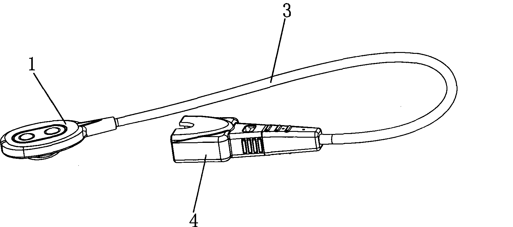
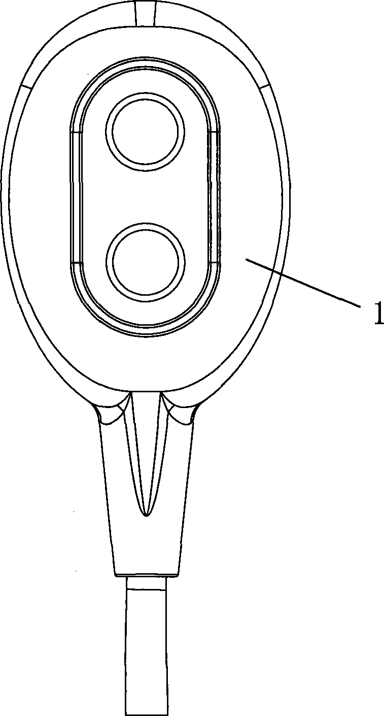
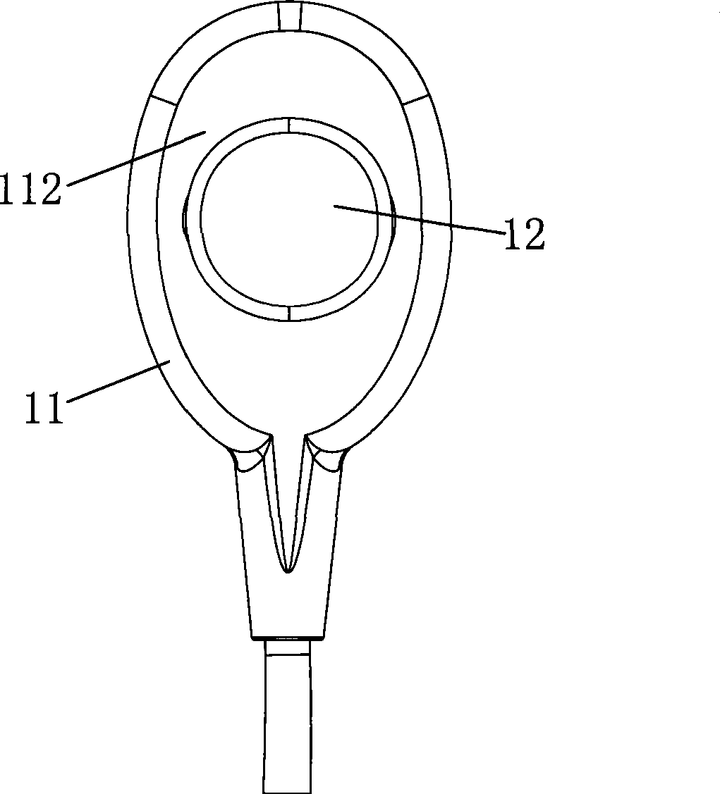
[0026] like Figure 1 to Figure 8 As shown, the forehead sensor fixing assembly of this embodiment includes a forehead sensor 1 and a strap 2 . The forehead sensor 1 is connected to one end of a cable 3 , and the other end of the cable 3 is connected to a connector 4 . The forehead sensor 1 includes a sensor body 11 and a fixing buckle 12 . The sensor body 11 has a substantially parallel front 111 and a back 112 , the front 111 is the side that attaches to the patient's forehead to collect measurement signals, and the back 112 is the side that is connected with the strap 2 for fixing. The fixing buckle 12 protrudes vertically from the back surface 112 of the sensor body 11. The fixing buckle 12 has a head 121 with a larger outer diameter and a neck 122 with a smaller outer diameter. The neck 122 is located between the head 121 and the sensor body. Between the back 112 of the sensor body, the neck 122 has a through hole 13, and the axis of the hole 13 is parallel to the back ...


PUM


Abstract

The invention discloses a forehead sensor, bandages and forehead sensor fixed assembly, including a forehead sensor and bandages, wherein, the forehead sensor includes a sensor body, the sensor body is provided with a front surface facing to the forehead and a back face in the trailing direction of the forehead, the bandage includes a strip body having front surface facing to the forehead and a back face in the trailing direction of the forehead, the back face of the sensor body protrudes a securing clasp which has a head and a neck with decreased external diameter, the neck is provided between the head and the back face, a first rotary attaching means is provided at one side of the back face of the sensor body, the bandage also includes a buttonhole and a second rotary attaching means, the buttonhole penetrates through the front face and back face of the strip body, the buttonhole is matched to the neck of the securing clasp, the head of the securing clasp and the back face of the sensor body clip the strip body, and the second rotary attaching means is provided on the strip body and is matched with the first rotary attaching means. By the dual localization to the forehead sensor, the forehead sensor can be tightly joint to the forehead.

Description

technical field [0001] The invention relates to a forehead sensor fixing assembly, in particular to a strap-type forehead sensor fixing assembly. Background technique [0002] With the development of science and technology, more and more sensors used on the forehead have begun to appear, such as sensors used to collect information such as blood oxygen, EEG, and bispectral index (BIS). These sensors are directly placed on the forehead of the human body but cannot be completely firmly fixed on the forehead, nor can they be closely attached to the forehead. At present, the fixing structures of these forehead sensors on the market mainly include adhesive structure and strap structure. The sticky structure is to add a layer of sticky paper on the surface of the sensor, and stick the sensor on the patient's forehead through the sticky paper, which requires a certain viscosity of the glue to achieve a better effect, but the sensor is removed from the patient's forehead When used, ...

Claims


Application Information

Patent Timeline
IPC IPC(8): A61B5/00
Inventor 曹建芳叶继伦
Owner SHENZHEN MINDRAY BIO MEDICAL ELECTRONICS CO LTD
Why Eureka
Try Eureka