Guide bar arrangement

A guide rail device and guide rail technology, which is applied in the direction of sawing equipment, chain saws, wood processing appliances, etc., can solve the problems of hindering oil delivery to the saw chain, easy to be blocked by sawdust or the like, and achieve the goal of reducing demand and improving lubrication Effect

Active Publication Date: 2013-04-03
ANDREAS STIHL AG & CO KG
View PDF1 Cites 0 Cited by
  • Summary
  • Abstract
  • Description
  • Claims
  • Application Information

AI Technical Summary

Problems solved by technology

This type of oil hole is prone to clogging with wood chips or similar during operation, which hinders the delivery of oil to the saw chain

Method used


Image

  • Guide bar arrangement
  • Guide bar arrangement
  • Guide bar arrangement

Examples


Embodiment Construction

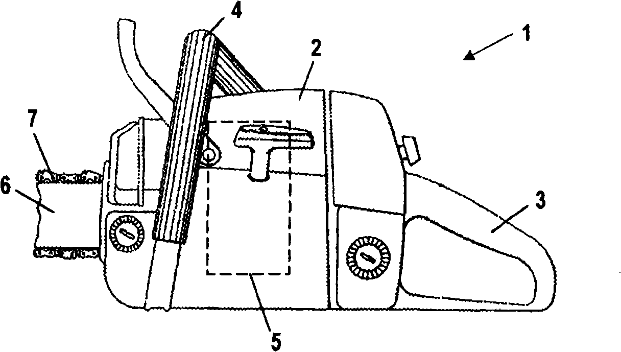
[0023] in figure 1 An embodiment of a hand-operated hand-held power saw 1 is shown in the figure, but the present invention can also be used in other power saws, such as a Hochentastern or a harvester, the so-called Harvester.

[0024] The power saw 1 has a housing 2. A rear handle 3 and an operating tube 4 are fixed on the housing. On the side of the housing 2 opposite to the rear handle 3, a guide rail 6 extends forward. A saw chain 7 is arranged around the guide rail. A drive motor 5 is provided in the housing 2. This motor drives the saw chain 7 to loop on the guide rail 6.

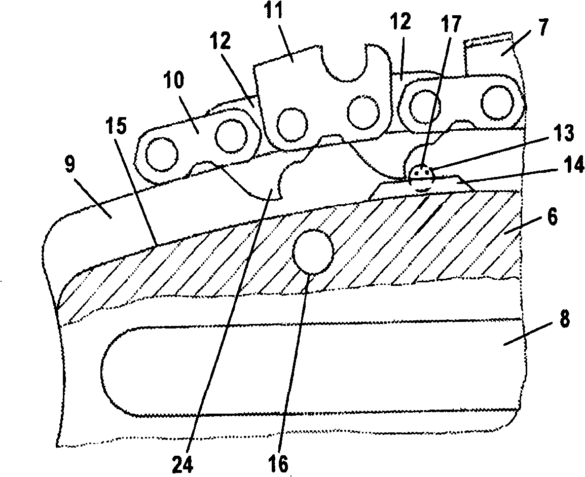
[0025] in figure 2 A cross-sectional view of the area of ​​the guide rail 6 fixed to the power saw 1 is shown in FIG. In order to be fixed on the power saw 1, the guide rail 6 has a longitudinal groove 8 and some transverse holes 16, in figure 2 Only one of the holes is shown in. An unillustrated tensioning device for the saw chain 7 can be engaged in this transverse hole 16. The guide rail 6 has a...


PUM


Abstract

A guide bar arrangement has a guide bar having a guide groove that extends about an outer circumference of the guide bar. A saw chain is driven in circulation in the guide groove about the guide bar. The guide groove is delimited by a groove base, a first sidewall and a second sidewall positioned opposite the first sidewall. The guide bar has an opening for supply of oil into the guide groove, wherein the opening extends from an exterior side of the guide bar, wherein the exterior side extends in a longitudinal direction of the guide bar, into the guide groove and opens in the first sidewall into the guide groove. An insert is secured in the opening and reduces a free flow cross-sectional area of the opening.

Description

Technical field [0001] The invention relates to a guide rail device. Background technique [0002] US 4,211,007 discloses a guide rail having two oil holes facing each other. These oil holes are arranged in the side wall of the guide groove. This type of oil hole is easily blocked by wood chips or the like during operation, which hinders the delivery of oil to the saw chain. Summary of the invention [0003] The task of the present invention is to provide a guide rail device that can ensure good lubrication of the saw chain. [0004] This task is accomplished by a guide rail device with a guide rail and a saw chain driven around it. The guide rail has a guide groove that extends on the outer periphery of the guide rail, and the saw chain is guided in the guide groove. The guide groove is limited by the bottom of the groove and two opposite side walls, and the guide rail has a function for conveying oil The port extends from the outer side surface of the guide rail extending in t...

Claims


Application Information

Patent Timeline
Patent Type & Authority Patents(China)
IPC IPC(8): B27B17/02B27B17/12
CPCB27B17/12
Inventor W·加尔斯特
Owner ANDREAS STIHL AG & CO KG
Why Eureka
Try Eureka