Improved book-binding machine handpiece

A binding machine and machine head technology, applied in the direction of binding, etc., can solve problems such as offside, damage to the machine head, machine head jamming, etc., and achieve the effect of increasing the binding speed, reducing the number of parts and ensuring the binding quality

Inactive Publication Date: 2009-06-24
淮南市耀华机械厂
View PDF0 Cites 8 Cited by
  • Summary
  • Abstract
  • Description
  • Claims
  • Application Information

AI Technical Summary

Problems solved by technology

In the domestic binding machine head, because the part layout of the binding mechanism itself limits the adjustment of the feeding length and the length of the movement stroke, and the part layout is limited by the head shell, when binding books of different thicknesses, it is necessary to complete all During the binding process, it is necessary not only to adjust the binding head to ensure the normal operation of the machine head, but also to adjust the binding stroke of the machine, otherwise the head jamming or offside phenomenon will occur, resulting in damage to the machine head

Method used


Image

  • Improved book-binding machine handpiece
  • Improved book-binding machine handpiece
  • Improved book-binding machine handpiece

Examples


Embodiment Construction

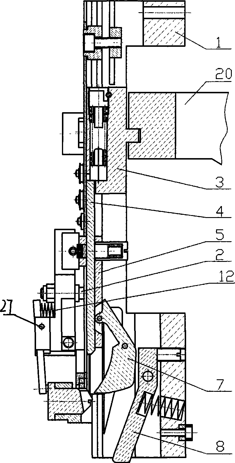
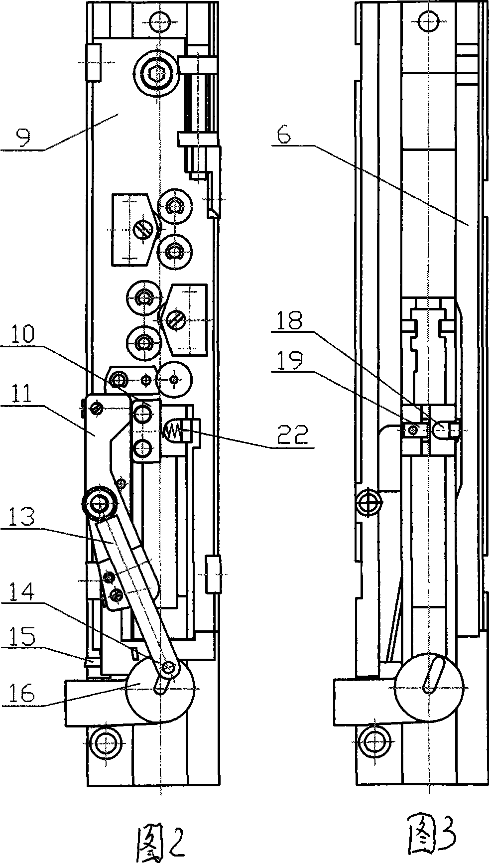
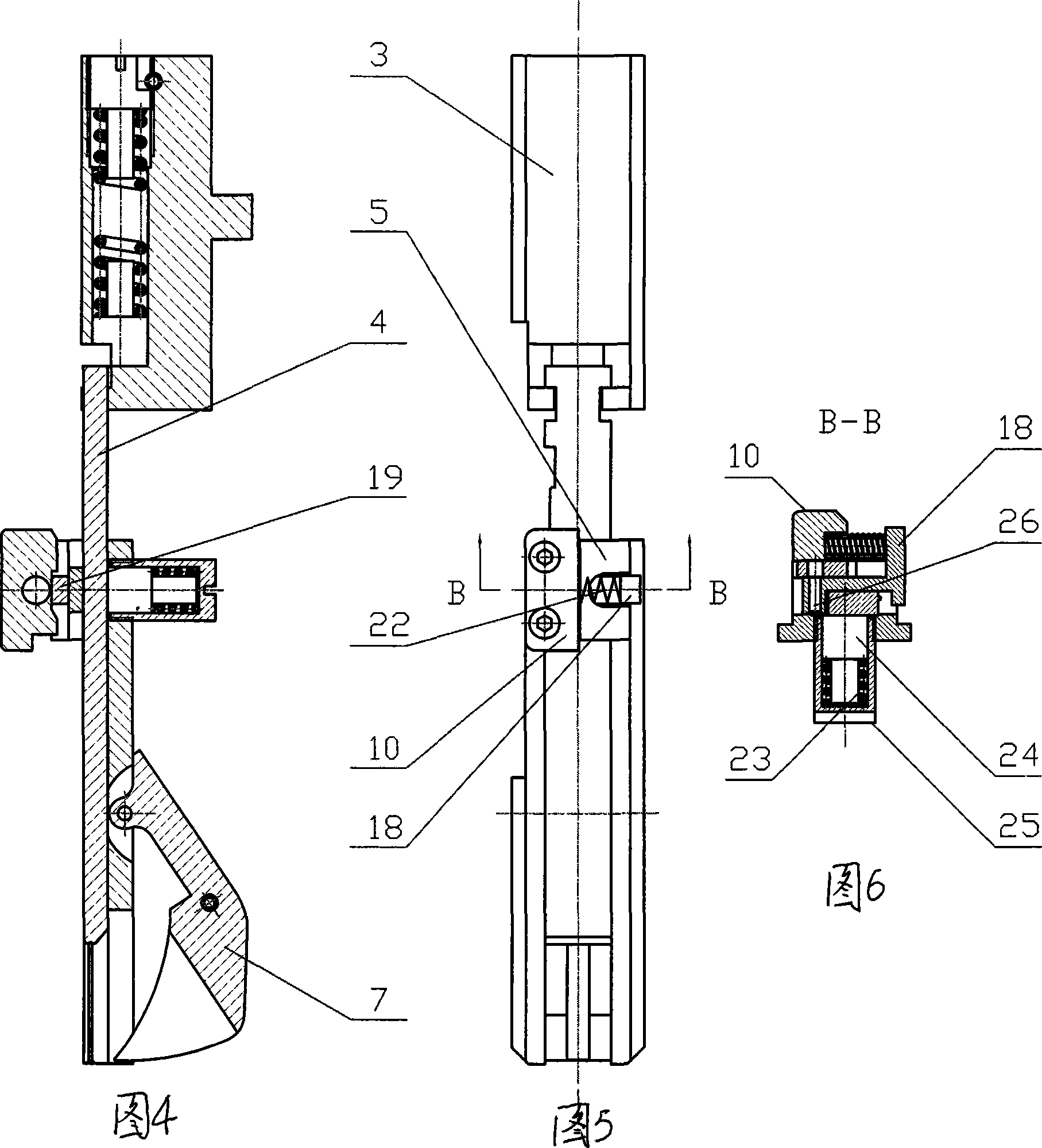
[0014] like figure 1 As shown in -6, an improved head of the binding machine, including the head shell, consists of a hook slide plate, a staple slide block, a hook slide plate, a tongue-shaped hook, a collision block, a toothed plate, a compression spring and a transmission collision block The set hook slide plate part composed of the machine head cover plate, eccentric shaft, straight seat, steel wire spring, pressure plate and cutter frame, the forming column part composed of the bracket and the forming column, and A control bar component consisting of a control bar, an adjustment seat, an adjustment screw, and a lock nut. The hook slide plate 5 is movably installed in the guide groove of the machine head housing 1, the middle part of the hook slide plate 4 is placed in the guide groove of the hook slide plate, and the upper part is hung on the groove of the staple slide block 3, and the staple slide block and the eccentric The binding hand 20 at the end of the wheel is at...


PUM


Abstract

The invention discloses an improved machine head of a binding machine, which belongs to the technical field of binding machinery and equipment. The invention aims to provide the improved machine head of the binding machine having the advantages of high binding quality, high binding speed and wide range of binding thickness. The improved machine head has the technical key points that a swinging block component consisting of a swinging block, a pressure arm, a pressure spring, a column and a spigot shaft is arranged between the lower part of an outer shell (1) of the machine head and a molding column (16); the swinging block (11) in the swinging block component is fixed on the outer shell of the machine head by taking the spigot shaft (2) as a rotating pair and is also adjacent to the left side of a striking block (10) on a hook sliding plate (5); the upper part of the pressure arm (13) is arranged in a guide slot of the swinging block and is also connected with the guide slot by a cylindrical pin to form the rotating pair; and the column (14) on the tail end of the pressure arm is inserted into a radial slot on the outer end surface of a forming column, and the pressure spring (12) is arranged between the upper end of the pressure arm and the swinging block. The improved machine head has the advantages of ensuring binding quality, improving binding speed, and making the binding thickness reach the range between 0.2 and 15 mm.

Description

technical field [0001] The invention relates to an improved binding machine head, which belongs to the technical field of binding machinery and equipment. Background technique [0002] At present, the maximum binding thickness of various types of multi-head binding machines produced in China is only 4 millimeters. In the domestic binding machine head, because the part layout of the binding mechanism itself limits the adjustment of the feeding length and the length of the movement stroke, and the part layout is limited by the head shell, when binding books of different thicknesses, it is necessary to complete all During the binding process, it is necessary not only to adjust the binding head to ensure the normal operation of the machine head, but also to adjust the binding stroke of the machine, otherwise the head jamming or offside phenomenon will occur, resulting in damage to the machine head. That is to say the key of the size of the binding thickness range is the movemen...

Claims


Application Information

Patent Timeline
Patent Type & Authority Applications(China)
IPC IPC(8): B42B4/00
Inventor 秦修智许强军
Owner 淮南市耀华机械厂
Why Eureka
Try Eureka