Supercharge Your Innovation With Domain-Expert AI Agents!

AT traction electric power supply system of 27.5KV AC electrification railway

A technology for traction power supply systems and electrified railways. It is applied in power lines, transportation and packaging, and vehicle components. It can solve the problems of difficult transformer manufacturing, increased traction network impedance, and increased cost, so as to facilitate daily maintenance and repair. The effect of reducing the number of projects and reducing the project cost

Inactive Publication Date: 2009-06-24
SOUTHWEST JIAOTONG UNIV
View PDF0 Cites 10 Cited by
  • Summary
  • Abstract
  • Description
  • Claims
  • Application Information

AI Technical Summary

Benefits of technology

This patented technology allows for better performance and efficiency during use compared to current methods such as AC induction motors. By connecting either the input terminal on each end from the primary coils to the middle point of the autotransformer without changing its polarity, this design can reduce voltages while still providing efficient operation. Additionally, the circuitry simplifies the overall design making it easier to maintain and operate over long periods of service due to fewer components needed. Overall, these technical improvements result in improved reliability, durable life span, lower operating costs, ease of installation, etc., leading to increased adoption across different industries worldwide

Problems solved by technology

The technical problem addressed in these patents relates to improving the performance and efficiency of electric vehicles used in high-power applications like highway transport systems without increasing their weight and costs associated with traditional power supplies.

Method used


Image

  • AT traction electric power supply system of 27.5KV AC electrification railway
  • AT traction electric power supply system of 27.5KV AC electrification railway
  • AT traction electric power supply system of 27.5KV AC electrification railway

Examples


Embodiment

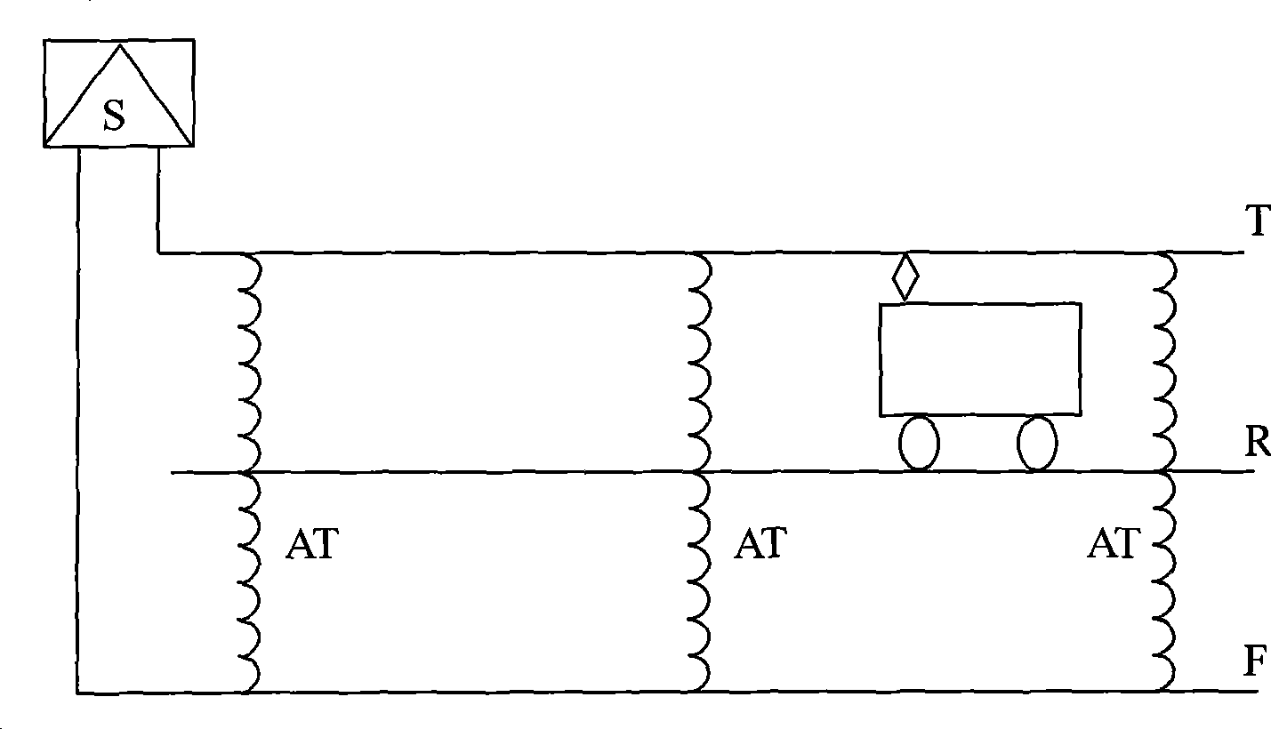
[0027] Figure 4 As shown, a specific embodiment of the present invention is a 27.5KV AC electrified railway AT traction power supply system, which consists of:

[0028] The output voltage of the traction transformer S in the traction substation is 27.5kV. One output terminal M of the traction transformer S is connected to the rail R, and the other output terminal N is connected to the positive feeder F of the railway traction network;

[0029] The railway traction network is equipped with an autotransformer AT with a transformation ratio of 2:1 every 10-20km. One end a of the autotransformer AT is connected to the railway contact line T, the middle point o is connected to the rail R, and the other end b is connected to the railway traction line. The positive feeder F of the network is connected.


PUM


Abstract

The invention relates to an AT traction power supply system of a 27.5KV alternating current gasification railway. The system comprises: the output voltage of a traction transformer (S) of a traction substation is 27.5kV; one output end (M) of the traction transformer (S) is connected with a steel rail (R); the other output end (N) is connected with a positive feeder (F) of a railway traction net; an autotransformer (AT) with transformation ratio of 2 to 1 is arranged in the railway traction net every other 10 to 20 km; one end (a) of the autotransformer (AT) is connected with a railway contact line (T); a center (o) is connected with the steel rail (R); and the other end (b) of the autotransformer (AT) is connected with the positive feeder (F) of the railway traction net. The system has the advantages of the AT power supply system and has small equipment investment, small engineering quantity and easy overhauling and maintenance; moreover, the system is easy to reconstruct the prior direct supply and BT mode railway, and is convenient to implement, and favorable for development of a high-speed overloading railway.

Description


Claims


Application Information

Patent Timeline
Owner SOUTHWEST JIAOTONG UNIV
Features
  • R&D
  • Intellectual Property
  • Life Sciences
  • Materials
  • Tech Scout
  • Unparalleled Data Quality
  • Higher Quality Content
  • 60% Fewer Hallucinations
Learn More