Smoke discharging pipeline

A technology of smoke exhaust pipes and gas pipes, which is applied in the direction of exhaust gas exhaust devices, combustion product treatment, combustion methods, etc., can solve the problems of inconvenience for residents in the use area, increase labor intensity and difficulty of installation or maintenance workers, and high manufacturing costs. Achieve the effects of reducing the intensity of installation and maintenance, facilitating promotion and application, and low production costs

Inactive Publication Date: 2009-06-24
韩文强
View PDF1 Cites 2 Cited by
  • Summary
  • Abstract
  • Description
  • Claims
  • Application Information

AI Technical Summary

Problems solved by technology

[0002] Now all kinds of residences use a common exhaust duct, and each household exhausts the indoor flue gas into the main duct through the air inlet on the main duct, and discharges it from the outlet of the roof. During the exhaust process, the smoke from the upper-floor residents will enter the room from the air inlet. When the wind is strong, the smoke exhausted by the upper-floor residents will return to the indoors of the lower-floor residents, which will bring a lot of inconvenience to the residents in the use area.
[0003] At present, those skilled in the art have been looking for various solutions, among which the patent ZL01136512.9 discloses a variable pressure exhaust duct, which adds a variable pressure plate in the smoke exhaust duct, and adds a guide tube to the main duct , check exhaust valve, etc. to solve the above problems, the structure is more complicated, the manufacturing cost is relatively high, and all components are fixed on the main pipeline with screws, etc., if one or several components are loose and fall, it is bound to It affects the use of the exhaust pipe below it, and it is very inconvenient to install and maintain, which increases the labor intensity and difficulty of the installation or maintenance workers, which is not conducive to the application and popularization of this pipe

Method used


Image

  • Smoke discharging pipeline
  • Smoke discharging pipeline
  • Smoke discharging pipeline

Examples


Embodiment Construction

[0015] The present invention will be further described below in conjunction with the accompanying drawings and specific embodiments.

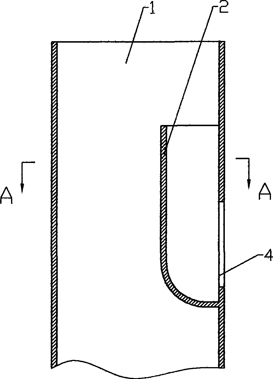
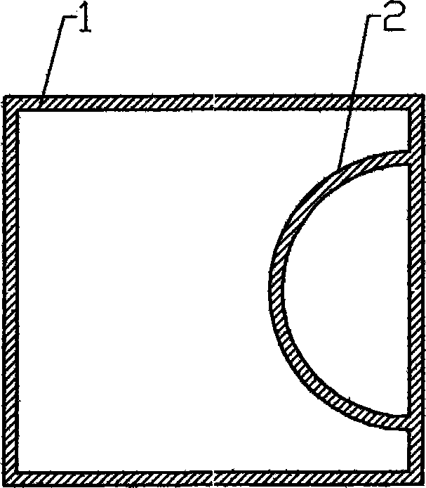
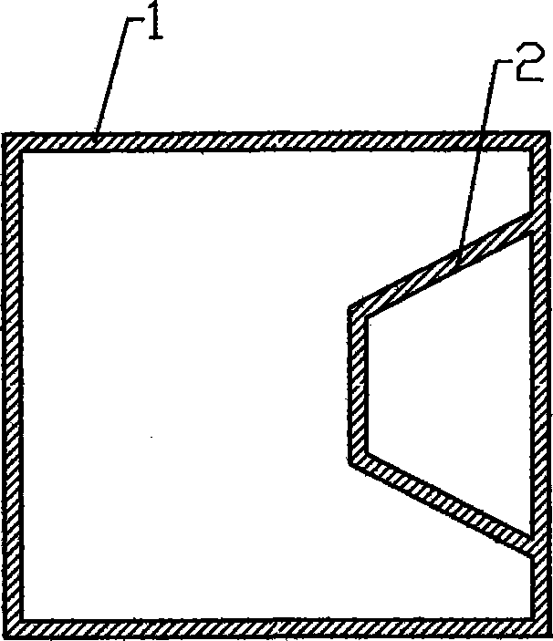
[0016] Such as figure 1 As shown, a smoke exhaust pipe includes a smoke exhaust pipe body 1, at least one air inlet 4 is provided on the smoke exhaust pipe body 1, and each air inlet 4 is provided with an exhaust pipe 2 to assist exhaust The pipe 2 is located inside the pipe body 1. The drainage aid pipe 2 is integrated with the pipe body 1. The drainage aid pipe 2 and the inner wall of the pipe body 1 form a flue gas outlet pipe that is closed at the lower end and has a diameter smaller than the inner diameter of the pipe body 1, namely The exhaust aid pipe 2 and the pipe body 1 are formed in the same mold at one time, that is, during casting, a structure of casting the exhaust aid pipe 2 is added to the casting mold, so that after the casting is completed, the exhaust aid pipe 2 and the smoke exhaust pipe 1 become one.

[0017] During the c...


PUM


Abstract

The invention discloses a pipeline for removing smoke, comprising a pipeline body which is provided with at least an air inlet, each air inlet is provided with an assisted discharge tube which is arranged inside the pipeline body, a section of smoke vent pipeline with lower end closed and diameter less than the inner diameter of the pipeline body is formed from the assisted discharge tube and the inner wall of the pipeline body; the assisted discharge duct and the pipeline body constitute a united structure, thus saving the process that the assisted discharge tube is additionally arranged when the pipeline is arranged, solving the problem that the assisted discharge tube falls off as bolts are loosened. The process from fission to integration of the assisted discharge tube and the pipeline for removing smoke is the result of repeated trial but is not obvious in the technical field, thus the pipeline for removing smoke is endowed with great features. The pipeline for removing smoke reduces the assembly and maintenance intensity of workers after the improvement, and has simple structure, low production cost and convenient popularization and application, thus making obvious progress.

Description

technical field [0001] The invention relates to a smoke exhaust pipe, in particular to a smoke exhaust pipe with an exhaust aid device. Background technique [0002] Now all kinds of residences use a common exhaust duct, and each household exhausts the indoor flue gas into the main duct through the air inlet on the main duct, and discharges it from the outlet of the roof. During the exhaust process, the smoke from the upper-floor residents will enter the room from the air inlet. When the wind is strong, the smoke from the upper-floor residents will return to the lower-floor residents, which will bring a lot of inconvenience to the residents in the use area. [0003] At present, those skilled in the art have been looking for various solutions, among which the patent ZL01136512.9 discloses a variable pressure exhaust duct, which adds a variable pressure plate in the smoke exhaust duct, and adds a guide tube to the main duct , check exhaust valve, etc. to solve the above probl...

Claims


Application Information

Patent Timeline
Patent Type & Authority Applications(China)
IPC IPC(8): F23J11/00
Inventor 韩文强
Owner 韩文强
Why Eureka
Try Eureka