

Ultrasonic self-calibration high-precision rain gauge
An ultrasonic and rain gauge technology, which is applied in the field of ultrasonic self-calibrating high-precision rain gauge and its measurement, can solve the problems of not meeting the requirements of rainfall measurement and the large range of rainfall observation, and achieve the effect of measuring rainfall and accurate rainfall
- Summary
- Abstract
- Description
- Claims
- Application Information
AI Technical Summary
Problems solved by technology
Method used
Image

Examples
Embodiment 1
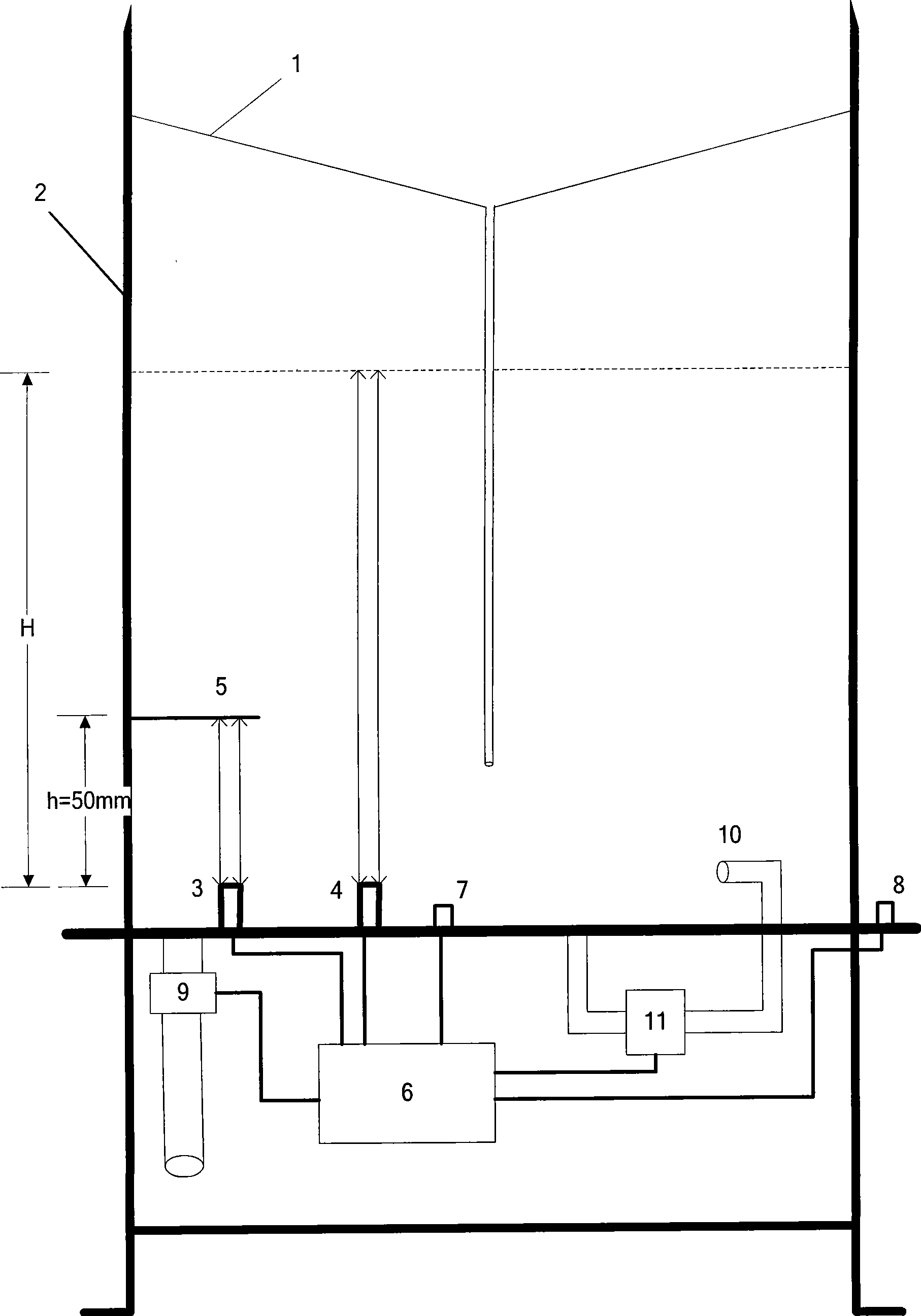
[0060]As shown in Figure 1(a), Embodiment 1 of the present invention includes a rain collector 1, a rain barrel 2, an ultrasonic transducer 3 for calibration, an ultrasonic transducer 4 for measurement, a calibration measuring tool 5, a controller 6, a rainwater Temperature sensor 7, rainfall temperature sensor 8, drainage system and cleaning system. The calibration gauge 5 is set in the rain gauge barrel 2, the calibration transducer 3 and the measurement transducer 4 have the same emission frequency, both are placed at the bottom of the rain gauge barrel 2, and are on the same horizontal plane, and the calibration transducer 3 is placed on the side of the calibration gauge 5 Directly below, the measuring transducer 4 deviates from the calibration gauge 5 . The correction measuring tool 5 is a wide stainless steel plate that emits ultrasonic waves from the complete reflection correction transducer 3, which is 25mm wide, 90mm long, and 1.5mm thick. The rain temperature sensor...
Embodiment 2
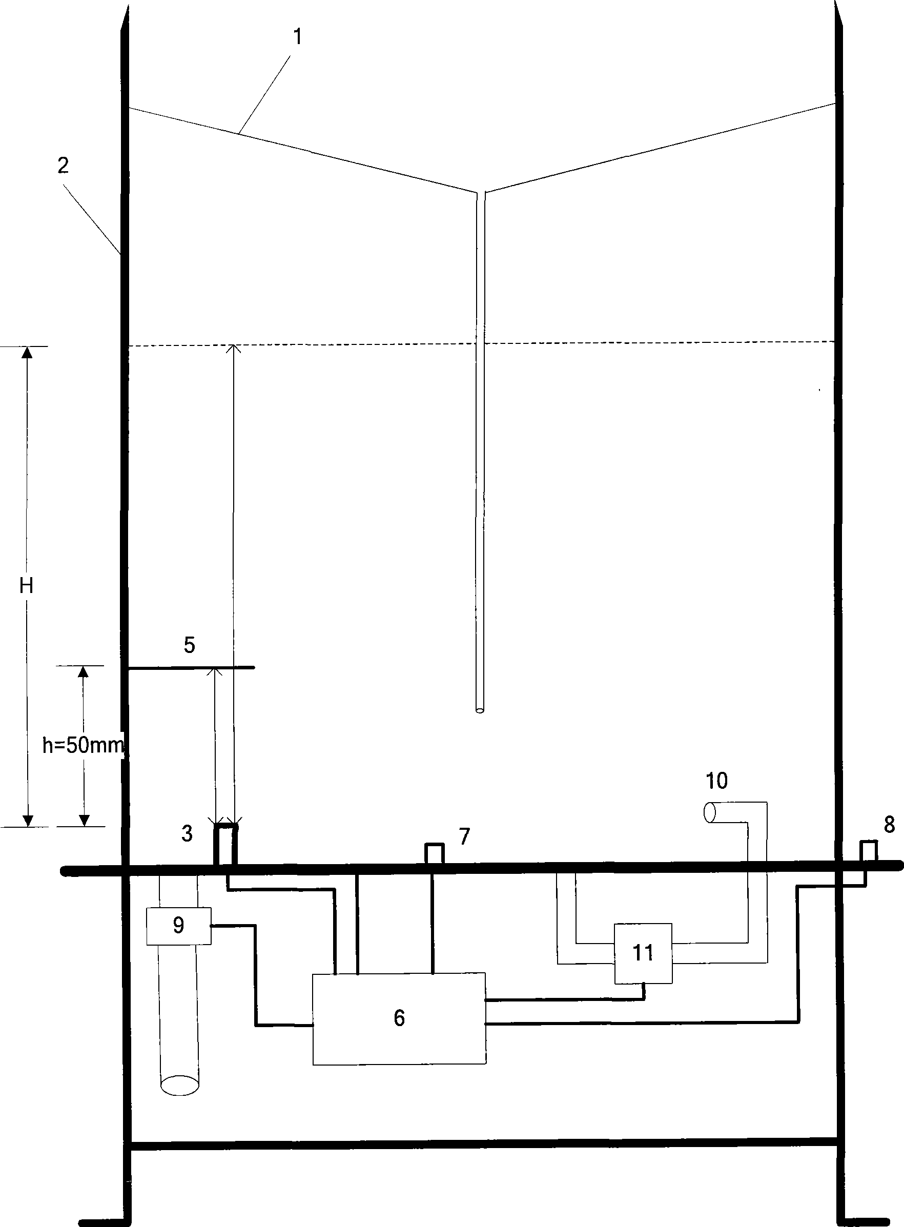
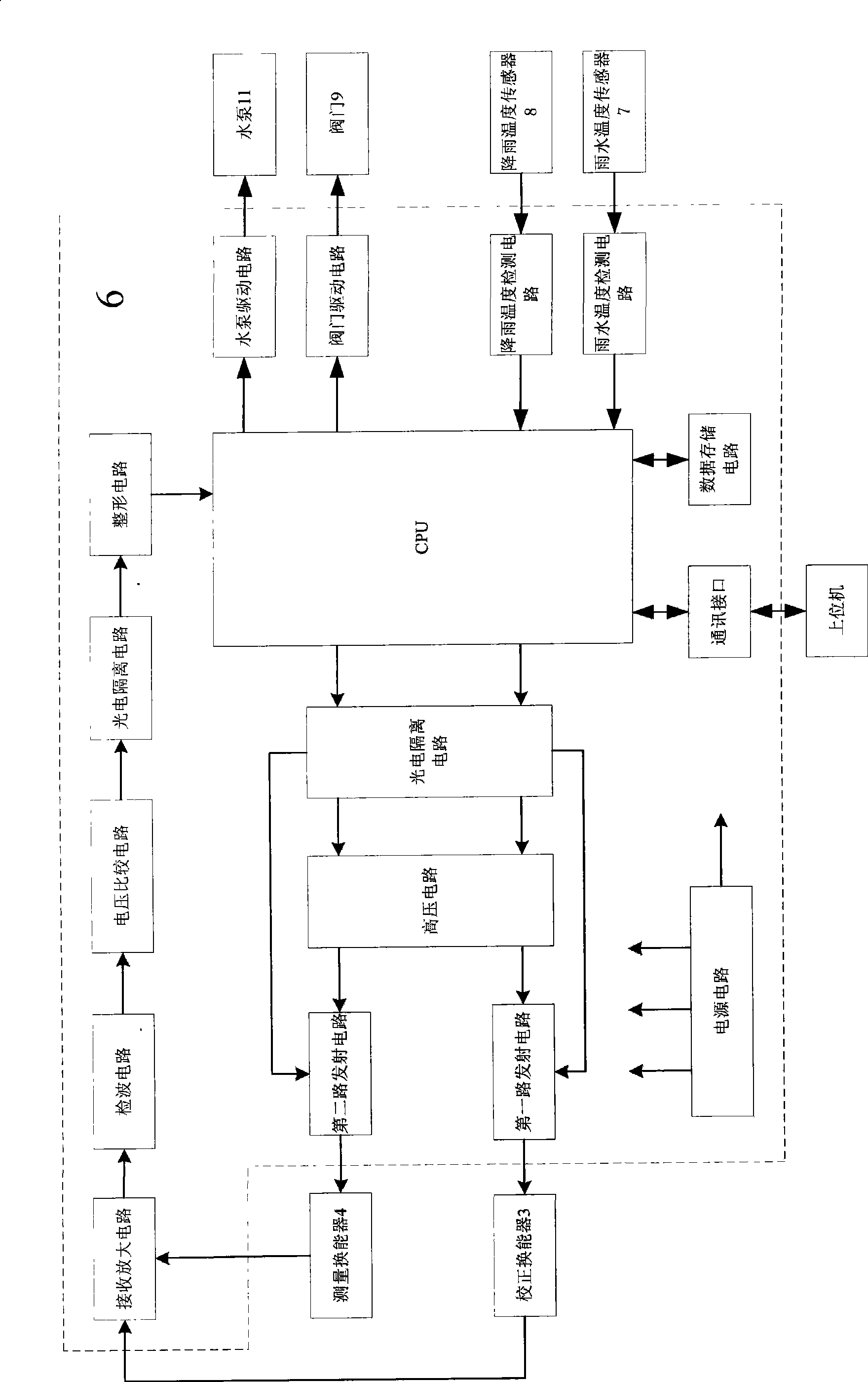
[0100] As shown in Figure 1(b), the difference between the second embodiment of the present invention and the first embodiment is that only one ultrasonic transducer 3 is used, and the calibration gauge 5 is narrower than that of the first embodiment, which is a partially reflective transducer 3 The narrow stainless steel plate that emits ultrasonic waves is 5mm wide, 90mm long, and 1.5mm thick. Part of the ultrasonic waves emitted by the transducer 3 is reflected on the surface of the calibration gauge 5 and received by the transducer 3, and the other part passes through the calibration gauge 5. The rainwater collected by the rain barrel 2 is reflected on the surface and received by the transducer 3. Correspondingly, as shown in FIG. 2( b ), the transmission output circuit in the controller 6 of the second embodiment includes a photoelectric isolation circuit, a high-voltage circuit, and a transmission circuit, and there is only one transmission circuit.
PUM
 Abstract
Description
Claims
Application Information