Pll circuit

A circuit and current technology, applied in the direction of electrical components, automatic power control, etc., can solve the problems of low performance, slow response characteristics, deviation of PLL circuit response characteristics, etc., and achieve the effect of less deviation

Inactive Publication Date: 2009-06-24
SEIKO INSTR INC
View PDF1 Cites 2 Cited by
  • Summary
  • Abstract
  • Description
  • Claims
  • Application Information

AI Technical Summary

Problems solved by technology

[0017] However, in the CMOS process, it is difficult for the voltage-current conversion unit 103A in the VCO 103 to have a response characteristic sufficiently corresponding to the sharp change when the voltage-current conversion of the input steep voltage output signal is performed. Figure 10 As shown, the waveform of the current output signal after the voltage-current conversion becomes blunt
[0018] As a result, even if the response characteristics of the loop filter 102 are improved, due to the slowness of the response characteristics of the voltage-current conversion unit 103A in the VCO 103, the theoretical design cannot be performed from the element characteristics.
[0019] In addition, due to manufacturing variations, the speed of voltage-current conversion varies, and as a result, the response characteristics of the PLL circuit also vary, and there is a problem that defective products increase during mass production.

Method used


Image

  • Pll circuit
  • Pll circuit
  • Pll circuit

Examples


Embodiment Construction

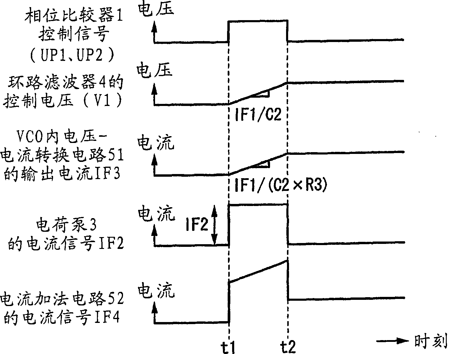
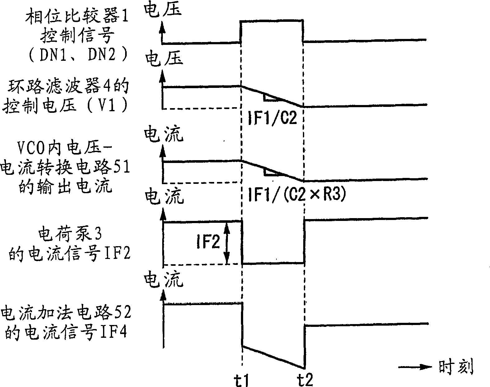
[0037] Hereinafter, a PLL circuit according to an embodiment of the present invention will be described with reference to the drawings. figure 1 It is a block diagram showing a configuration example of the PLL circuit of this embodiment.

[0038] In this figure, the PLL circuit of this embodiment includes a phase comparison circuit 1 , a charge pump 2 , a charge pump 3 , a loop filter 4 , a VCO 5 , and a frequency divider 6 . In addition, the VCO 5 is composed of a voltage-current conversion circuit 51 , a current addition circuit 52 , and a current control oscillation circuit 53 .

[0039] The frequency divider 6 divides the frequency fout of the pulse signal Fout output by the VCO5 by 1 / N, and outputs a frequency-divided pulse signal whose frequency is fout / N. Accordingly, the frequency fout of the pulse signal Fout is N times the frequency fin of the reference pulse signal Fin.

[0040] The phase comparison circuit 1 detects the phase difference between the frequency-div...


PUM


Abstract

The PLL circuit includes: a voltage control oscillating circuit including: a voltage-current converter circuit; a current adder; and a current control oscillating circuit, the voltage control oscillating circuit outputting a pulse having a frequency corresponding to a control voltage and a control current; a phase detector which outputs a first control signal and a second control signal based on a phase difference between the pulse and a reference pulse having a frequency which should be generated by the voltage control oscillating circuit; a first charge pump circuit which outputs one of a first charge current and a first discharge current in accordance with the first control signal; a loop filter which generates the control voltage in accordance with the one of the first charge current and the first discharge current, and then outputs the generated control voltage to the voltage control oscillating circuit; and a second charge pump circuit which generates the control current serving as one of a second charge current and a second discharge current in accordance with the second control signal, and then outputs the generated control current to the voltage control oscillating circuit.

Description

technical field [0001] The present invention relates to a PLL circuit, and more particularly to a PLL circuit in which the occurrence of characteristic deviation is reduced. Background technique [0002] Conventionally, it has been widely used as a pulse generating circuit provided in a semiconductor integrated circuit, especially in a mobile phone and a wireless LAN (local area network) in the field of wireless communication. [0003] The above PLL circuit as Figure 6 As shown, it is composed of a phase comparator 100 , a charge pump 101 , a loop filter 102 and a VCO (voltage controlled oscillator circuit) 103 . [0004] The phase comparator 100 performs a phase comparison between the output pulse output from the PLL circuit and the input pulse input, and outputs a control signal UP to the charge pump circuit 101 through which the charging current IUP flows when the phase of the output pulse lags behind the input pulse. , when the phase of the output pulse is advanced com...

Claims


Application Information

Patent Timeline
Patent Type & Authority Applications(China)
IPC IPC(8): H03L7/06H03L7/089H03L7/18
CPCH03L7/093H03L7/0893H03L7/08
Inventor 须藤徹
Owner SEIKO INSTR INC
Why Eureka
Try Eureka