
Liquid treating apparatus, air-conditioning apparatus, and humidifier

A technology for liquid treatment and air-conditioning devices, which is applied in air humidification systems, air treatment details, water/sewage treatment, etc. problems, to achieve the effect of improving gas-liquid contact efficiency, improving purification capacity, and improving sterilization capacity and purification capacity

Inactive Publication Date: 2009-06-24
DAIKIN IND LTD
View PDF1 Cites 8 Cited by
  • Summary
  • Abstract
  • Description
  • Claims
  • Application Information

AI Technical Summary

Problems solved by technology

[0008] As shown in Patent Document 1, when ultraviolet rays are used to treat condensed water, the sterilizing ability and purifying ability for condensed water are limited, and there is a possibility that the size of the air conditioner may be increased due to the large size of the ultraviolet irradiation device.
In addition, although antibacterial treatment is carried out on the surface of the drip tray, or the method of adding chemicals to condensed water for sterilizing treatment is also known, but because the durability of its bactericidal ability is limited, it is impossible to ensure the long-term protection of condensed water. water quality

Method used


Image

  • Liquid treating apparatus, air-conditioning apparatus, and humidifier
  • Liquid treating apparatus, air-conditioning apparatus, and humidifier
  • Liquid treating apparatus, air-conditioning apparatus, and humidifier

Examples


Embodiment approach 1

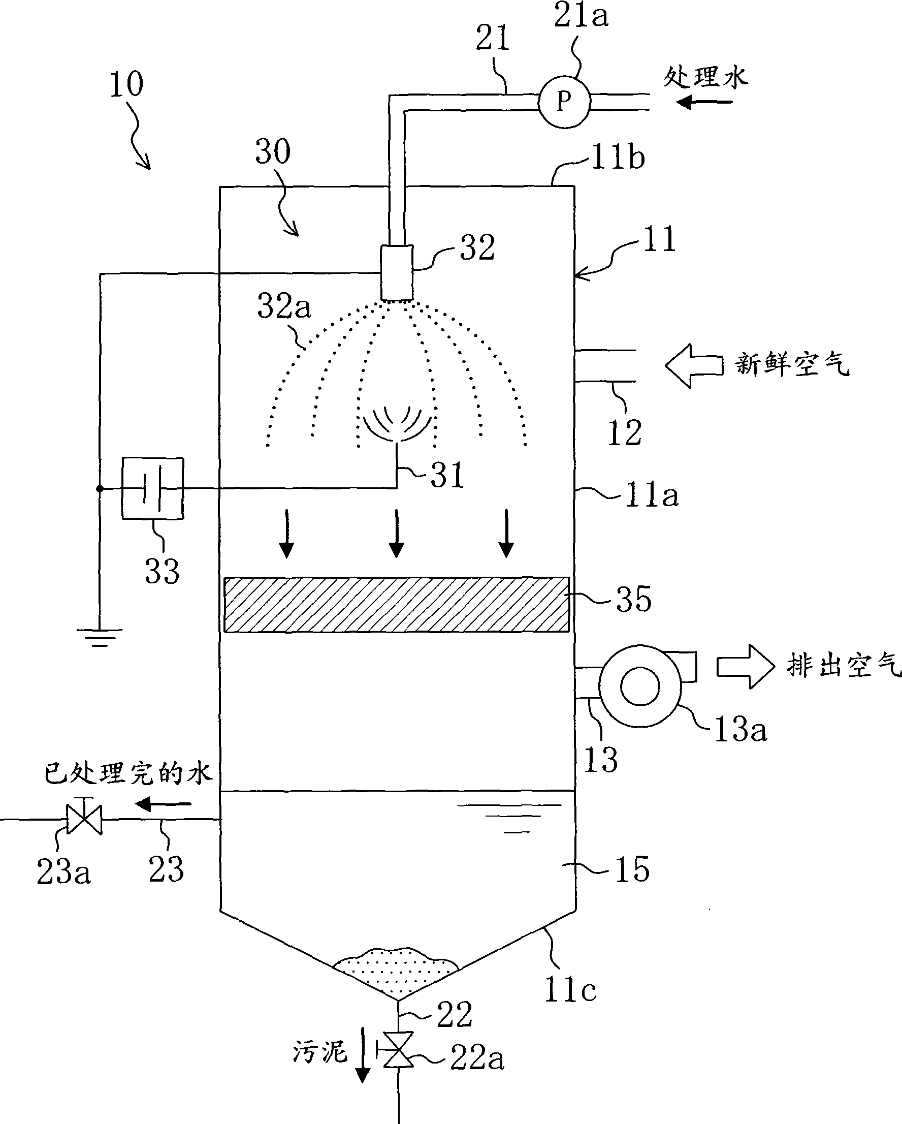
[0083] The liquid treatment device 30 according to Embodiment 1 of the present invention is applied to the waste water treatment system 10 for treating liquids (treated water) such as industrial waste water and sewage.

[0084] Such as figure 1As shown, the wastewater treatment system 10 has a hollow and elongated liquid treatment tower 11 . The liquid processing tower 11 is composed of a cylindrical trunk portion 11a, a top plate portion 11b formed at the upper end of the trunk portion 11a, and a conical bottom plate portion 11c protruding downward from the trunk portion 11a. In addition, a reaction tank 15 for temporarily storing treated water is formed at the bottom of the liquid treatment tower 11 .

[0085] Intake ports 12 and exhaust ports 13 are formed on the side surfaces of the trunk portion 11 a of the liquid processing tower 11 . The air inlet 12 is for introducing fresh air into the interior of the liquid processing tower 11 . The exhaust port 13 is for discharg...

Embodiment approach 4

[0165] The liquid processing device 30 according to Embodiment 4 of the present invention is mounted on a humidifier 70 for humidifying a room.

[0166] Such as Figure 10 As shown, the humidifier 70 has a rectangular humidifier housing 71 . A humidified air discharge port 72 is formed on a side surface of the humidifier casing 71 . In addition, the humidification water tank 65, the steam generator 73, and the liquid processing device 30 are accommodated in the humidification cabinet 71.

[0167] Humidification water is stored in the humidification water tank 65 . In addition, an inlet for supplying humidifying water is formed on the upper part of the humidifying cabinet 71, and humidifying water can be replenished as necessary.

[0168] The steam generator 73 is arranged near the humidified air outlet 72 . The steam generator 73 is connected to the humidification water tank 65 through the humidification water supply pipe 66 . The steam generator 73 heats the humidificati...


PUM


Abstract

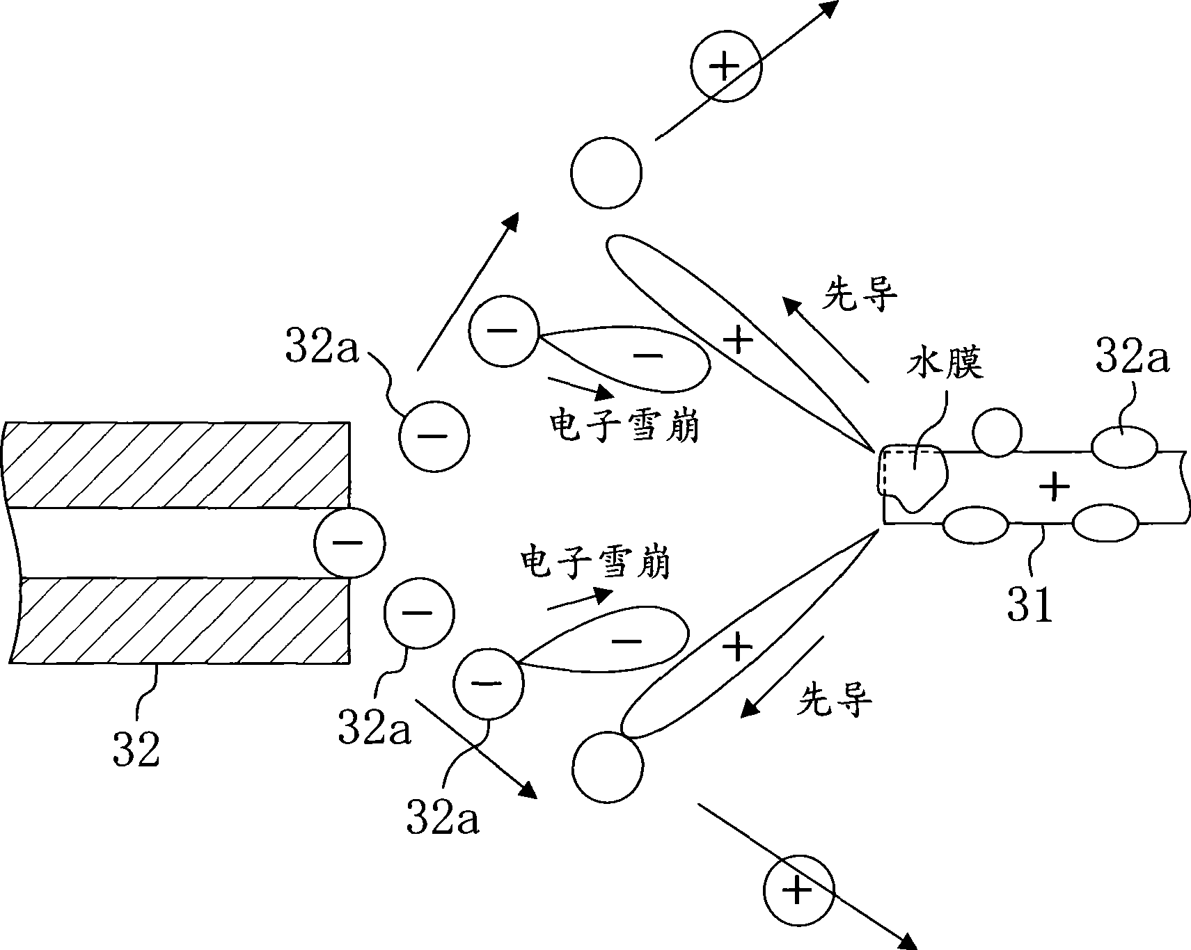
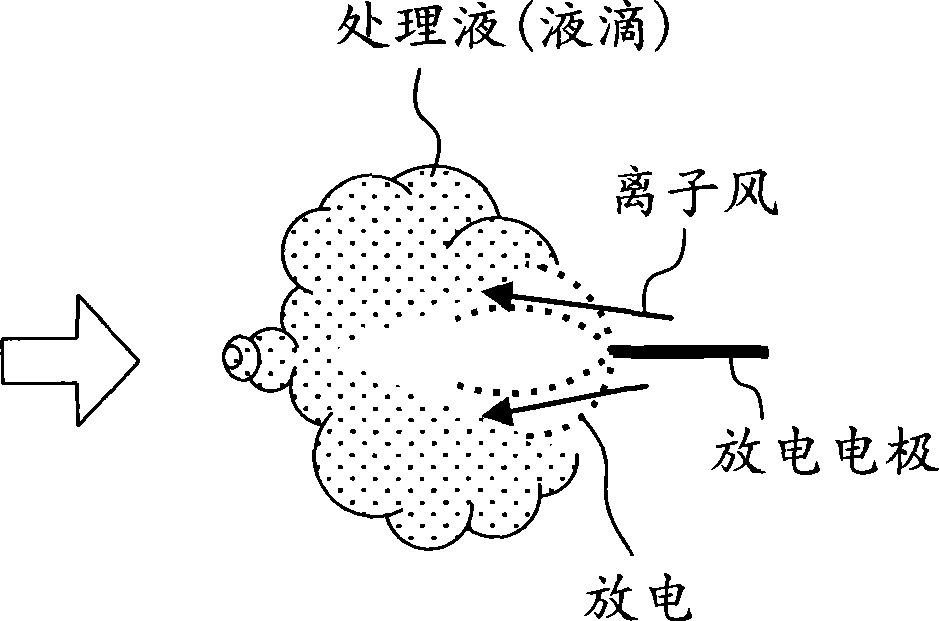
The present invention provides a liquid treating apparatus, an air conditioning device and a humidifier. The liquid treating apparatus comprises a discharge electrode (31) and an injector (32) arranged to confront each other. The discharge electrode (31) and the injector (32) are fed inbetween with a potential difference by a power source (33). As a result, a streamer discharge is established from the discharge electrode (31) toward liquid droplets (32a) injected from the injector (32). Active seeds produced according to the streamer discharge are absorbed into the liquid droplets (32a) so that the water to be treated is sterilized and cleaned.

Description

technical field [0001] The present invention relates to a liquid treatment device for treating liquid, an air conditioner having the liquid treatment device, and a humidifier. Background technique [0002] Conventionally, liquid processing apparatuses for purifying a processing liquid, etc. are widely known. For example, Patent Document 1 discloses a liquid treatment device that purifies condensed water collected in a drip pan of an air conditioner. [0003] In this air conditioner, a heat exchanger is provided in the indoor unit. When the air to be processed is cooled in the heat exchanger, moisture in the air condenses to generate condensed water. Therefore, in such an air conditioner, a drain pan for recovering condensed water is provided below the heat exchanger. [0004] In addition, when the condensed water accumulates in the drip pan for a long time, bacteria in the condensed water multiply, which causes water pollution of the condensed water and generation of an u...

Claims


Application Information

Patent Timeline
Patent Type & Authority Applications(China)
IPC IPC(8): B01J19/08F24F6/14C02F1/48F24F13/22F24F6/00
CPCF24F13/222F24F2006/006C02F1/4608F24F2203/1032B01J19/08C02F1/48F24F6/00F24F13/22
Inventor 茂木完治大堂维大田中利夫秋山竜司
Owner DAIKIN IND LTD
Learn More