Injection nozzle for arrangement in an injection mould

A die-casting mold and nozzle technology, applied in the field of die-casting spray, can solve problems such as damage and disadvantage of die-casting nozzles and connecting cables, and achieve the effect of easy installation

Inactive Publication Date: 2012-09-05
京特热渠道有限公司
View PDF2 Cites 0 Cited by
  • Summary
  • Abstract
  • Description
  • Claims
  • Application Information

AI Technical Summary

Problems solved by technology

[0004] It has been found in the known high-temperature channel nozzles or low-temperature channel nozzles that they are installed in a fixed mold plate, where they are generally in a distributor plate for the material melt, which is disadvantageous.
Possible leaks between the die casting nozzle and the distributor lead to unhindered diffusion of the material melt and possible damage to the die casting nozzle and connecting cables

Method used


Image

  • Injection nozzle for arrangement in an injection mould
  • Injection nozzle for arrangement in an injection mould
  • Injection nozzle for arrangement in an injection mould

Examples


Embodiment Construction

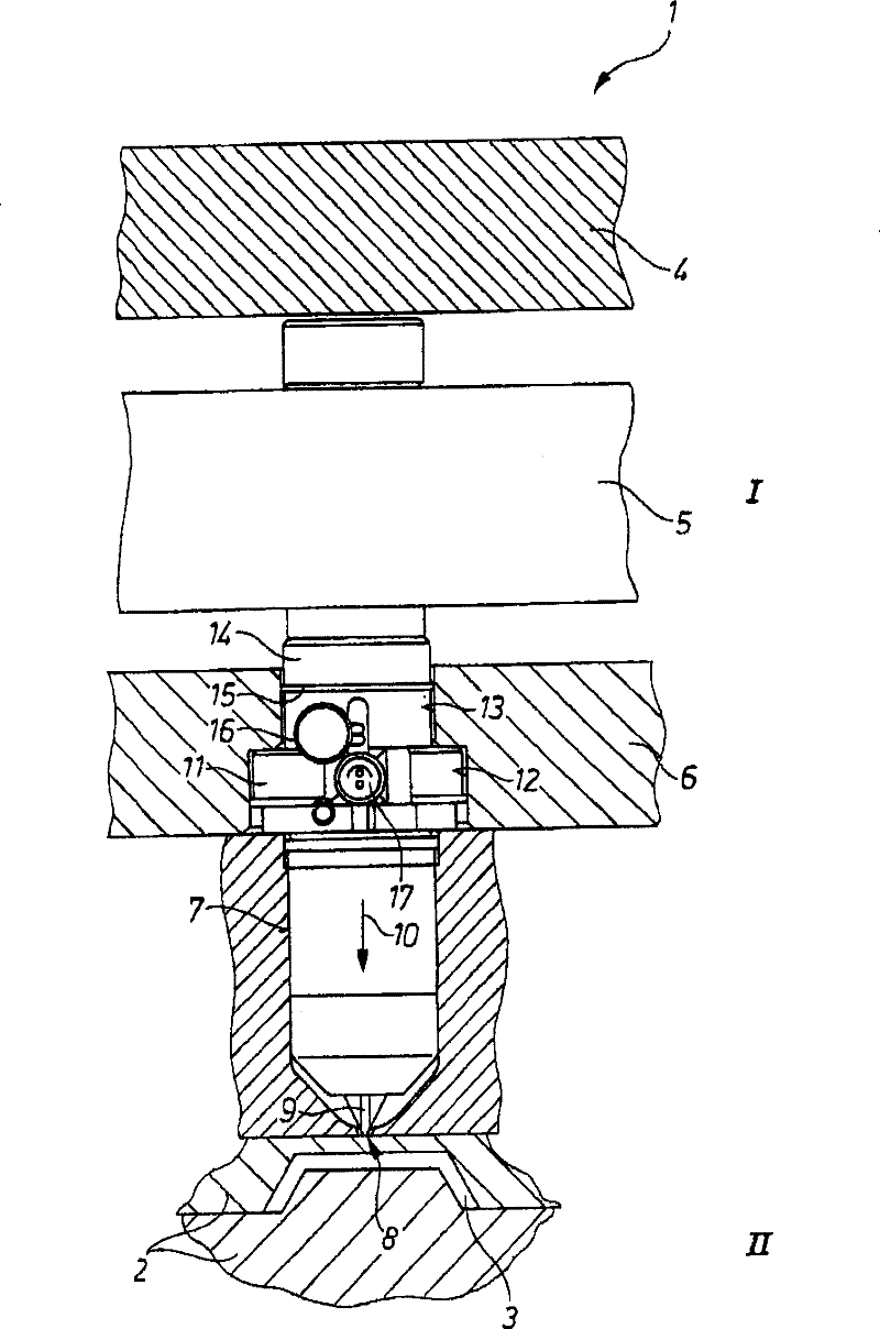
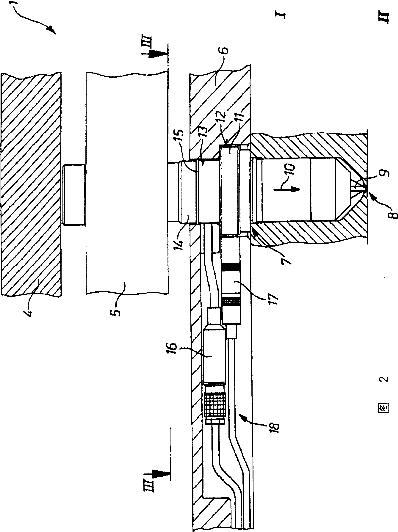
[0021] The die-casting mold 1 shown in the drawing consists of a plurality of plates on its fixed mold side I and on its mold side II which has a separable mold part which has a cavity plate 2 in which Machining out model cavity 3 (see figure 1 ). Among these plates are shown on the fixed mold side I a back or mold fastening base plate 4 , a distributor plate 5 with not shown flow channels, and a frame plate or intermediate plate 6 . In the die-casting mold 1 from the front, starting from the mold side II, an die-casting nozzle, which is designed as a high-temperature channel nozzle 7 in the exemplary embodiment, is inserted. This nozzle has a flow channel 9 leading to the nozzle tip 8 in a centered sleeve for the metal melt introduced from the distributor plate 5 according to the arrow 10 in the injection direction. Come out from the nozzle tip 8 and flow into the model cavity 3 of the cavity plate 2, as by figure 1 as visible.

[0022] The die-casting nozzle or the high-...


PUM


Abstract

In the case of an injection nozzle, in particular hot-runner nozzle (7), for arrangement in an injection mould (11) which has a relatively large number of plates as a function of the configuration, and which has, on its solid mould side (I), at least one platen (4) and one feed plate (5), and, on its mould side (II) at least one cavity plate (2), at the mould cavity (3) of which the nozzle point (8) is used, where the hot-runner nozzle (7) has been formed with a housing collar (11) and has been formed in a central material tube with a flow channel (9) for a material melt leading to the nozzlepoint (8), and has connections for a heating system (16) and / or cooling system and temperature sensor (17), the injection nozzle (7) has been incorporated into the injection mould (1) from the mould side (II) with sealing with respect to the feed plate (5).

Description

technical field [0001] The invention relates to a die-casting nozzle, in particular a high-temperature channel nozzle, which is intended to be arranged in a die-casting mold which, depending on its structure, has a plurality of plates and has at least one rear plate or mold fastening base on its fixed mold side. and a distributor plate with at least one cavity plate on its mold side, on the mold pocket of which the nozzle tip is inserted, wherein the high temperature channel nozzle is designed with a housing collar and in a central material tube There is a flow channel for the material melt that opens into the nozzle tip, as well as connections for the heating system and temperature sensors. Background technique [0002] A die-casting nozzle of this type is known from DE 195 42 237 B4, which is designed as a high-temperature channel nozzle with an integrated electrical heating element and has a central hole as a flow channel for conveying the thermoplastic melt up to the noz...

Claims


Application Information

Patent Timeline
Patent Type & Authority Patents(China)
IPC IPC(8): B29C45/27
CPCB29C2045/2775B29C45/27B29C2045/2719B22D17/2023B29C45/20
Inventor H·冈瑟
Owner 京特热渠道有限公司
Why Eureka
Try Eureka