
Stacked compression release valve

A pressure reducing valve and superimposed technology, applied in the field of hydraulic control valve, can solve the problems of inconvenient use, insufficient compact installation of the pressure reducing valve, and no secondary oil circuit pressure protection, etc., so as to reduce the pressure measuring port and reduce extravasation. The effect of missing links and reducing process holes

Inactive Publication Date: 2009-07-01
SHANGHAI LIXIN HYDRAULIC
View PDF0 Cites 16 Cited by
  • Summary
  • Abstract
  • Description
  • Claims
  • Application Information

AI Technical Summary

Problems solved by technology

The current pressure reducing valve is inconvenient to use because the installation is not compact enough and there is no secondary oil circuit pressure protection

Method used


Image

  • Stacked compression release valve
  • Stacked compression release valve

Examples


Embodiment

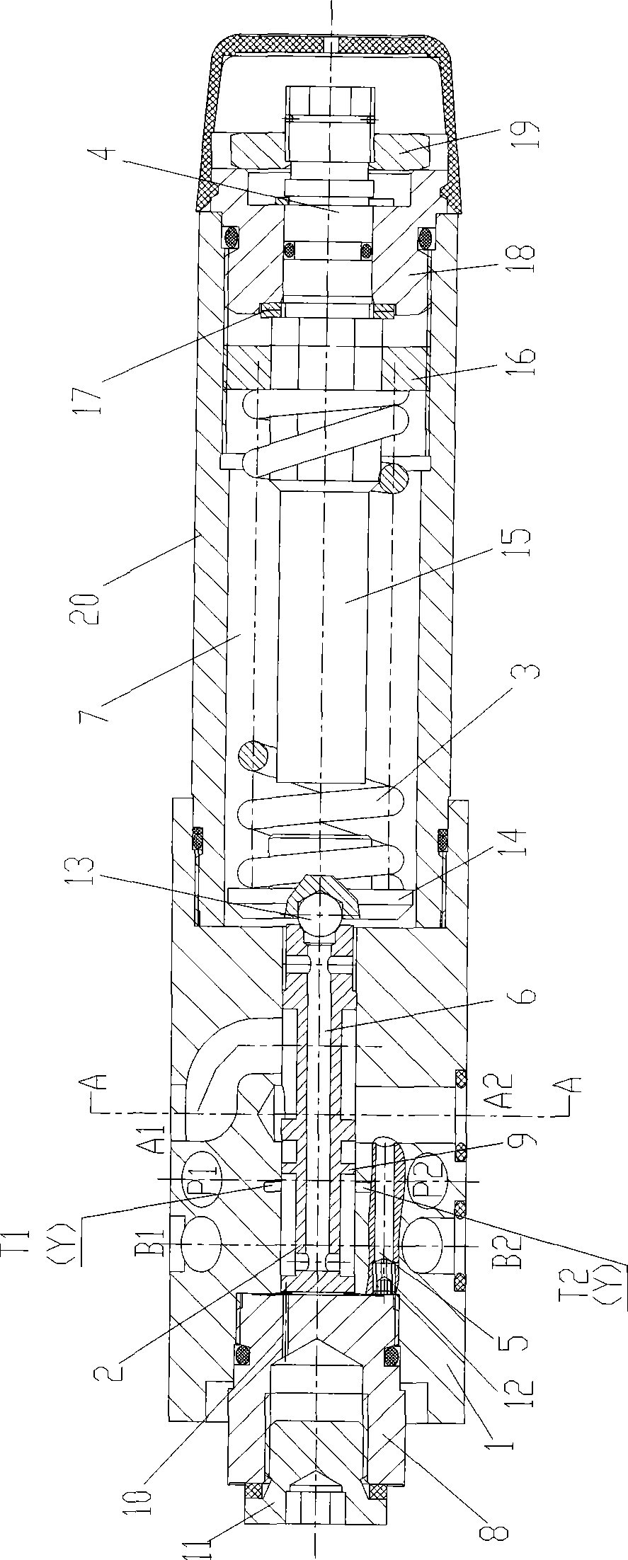
[0027] by figure 1 shown for explanation. In the static position, the valve is normally open and oil can flow freely from A1 to port A2. The pressure of the oil port A2 acts on the piston area opposite to the spring 3 through the control oil circuit 5 at the same time. When the pressure of oil port A2 exceeds the setting value of spring 3, the control spool 2 moves to the control position, and the pressure of oil port A2 remains stable. The signal and control oil are provided from the inside of oil port A2 through the damper 12 and the control oil passage 5. If the pressure of oil port A2 continues to rise due to the external force acting on the actuator, the control spool 2 will continue to move in the direction of the spring 3. In this way, the oil port A2 communicates with the oil tank through the spool shoulder 9 on the control piston 2 . Excess oil flows back to the tank to prevent further pressure build-up. The spring chamber 7 drains oil from the outside to the fue...


PUM


Abstract

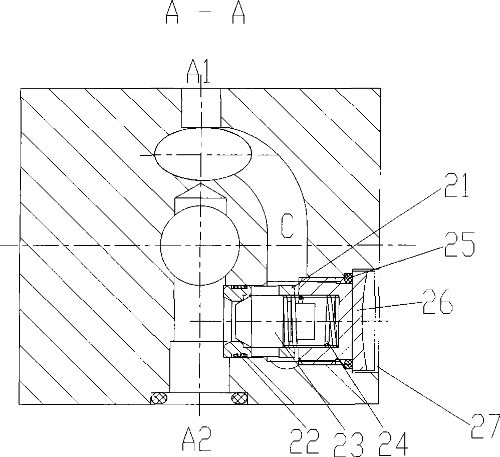
The present invention discloses a overlaid compression release valve hydraulic controlling valve field, which includes a valve body, an adjust element that mounted on the right end of the valve body, and a threaded sleeve mounted on the left end of the valve body; a valve body main hole is made by casting inside the valve body; P1, P2, A1, A2, B1, B2, T1, T2 flow passage, wherein P1 communicates with P2, A1 and A2 communicated through the main hole, B1 communicates with B2, T1 communicates with T2 and passes through the main hole; a C flow passage is set bypass the lateral surface of the main hole between the valve body A1 and the flow passage A2; a one-way valve hole is set on the lateral surface of the valve body; a one-way valve is mounted inside the one-way valve; one end of the one-way valve communicates with the flow passage A2 and the other end communicates with the outer wall of the valve body, the top end communicates with the flow passage C, and the one-way valve allows oil can only flow from oil port A2 to oil port A1. The beneficial effect of the invention is that inside of the overlaid one-way valve adopts pouring flow passage which simplifies structure and reduces fabrication holes; a selectable one-way valve is added to become a one-way compression release valve so as to make oil flows freely in opposite direction.

Description

Technical field: [0001] The invention relates to the field of hydraulic control valves, in particular to a superimposed pressure reducing valve used for reducing pressure in a hydraulic system. Background technique: [0002] The pressure reducing valve is a kind of valve that uses the opening degree of the opening and closing parts in the valve body to adjust the flow of the medium and reduce the pressure of the medium. within a certain range. The current pressure reducing valve is inconvenient to use because the installation is not compact enough and there is no secondary oil circuit pressure protection. Invention content: [0003] The technical problem to be solved by the present invention is to provide a superimposed pressure reducing valve with secondary oil circuit pressure protection, and a check valve can be selected. [0004] The technical scheme that the present invention adopts for solving technical problems is: [0005] A superimposed pressure reducing valve,...

Claims


Application Information

Patent Timeline
Patent Type & Authority Applications(China)
IPC IPC(8): F15B13/02F16K15/00
Inventor 袁才富何俊朱剑根沈至伟
Owner SHANGHAI LIXIN HYDRAULIC
Learn More