Pressure test method for power station valve

A power station valve and test method technology, which is applied in the direction of measuring the increase and decrease rate of the fluid, using liquid/vacuum degree to measure the liquid tightness, etc., can solve internal leakage, material is prone to creep, and the quality of the valve cannot be accurately measured conditions and other issues, to achieve a wide range of applications, good operability and accuracy, accurate and reliable experimental methods

Inactive Publication Date: 2011-03-30
SUZHOU SAIHUA INSTR CONTROL CO LTD
View PDF0 Cites 0 Cited by
  • Summary
  • Abstract
  • Description
  • Claims
  • Application Information

AI Technical Summary

Problems solved by technology

[0005] However, since the above-mentioned pressure test methods are all carried out at a lower temperature (not higher than 52°C) or normal temperature, which is quite different from the actual temperature under the working conditions of the power station valve, it is impossible to accurately measure the quality of the valve. However, under the working environment of high temperature and high pressure, the material of the valve is prone to creep, which leads to leakage or internal leakage after some qualified valves in the above pressure test are used in the actual power station working environment.

Method used


Image

  • Pressure test method for power station valve
  • Pressure test method for power station valve
  • Pressure test method for power station valve

Examples


Embodiment 1

[0028] A sealing test method for a valve in a power station. The valve to be tested is connected to the test pipeline, and the connection is set according to the requirements of the sealing test. First, the valve is heated to a set temperature, and the set temperature is 37-700 ° C, and then filled with helium. , do a sealing test with the gauge pressure not lower than 1.1 times the nominal pressure, and continue for the set time under the heat preservation and pressure holding state. If the pressure value drops beyond the set standard, it will be judged as unqualified.

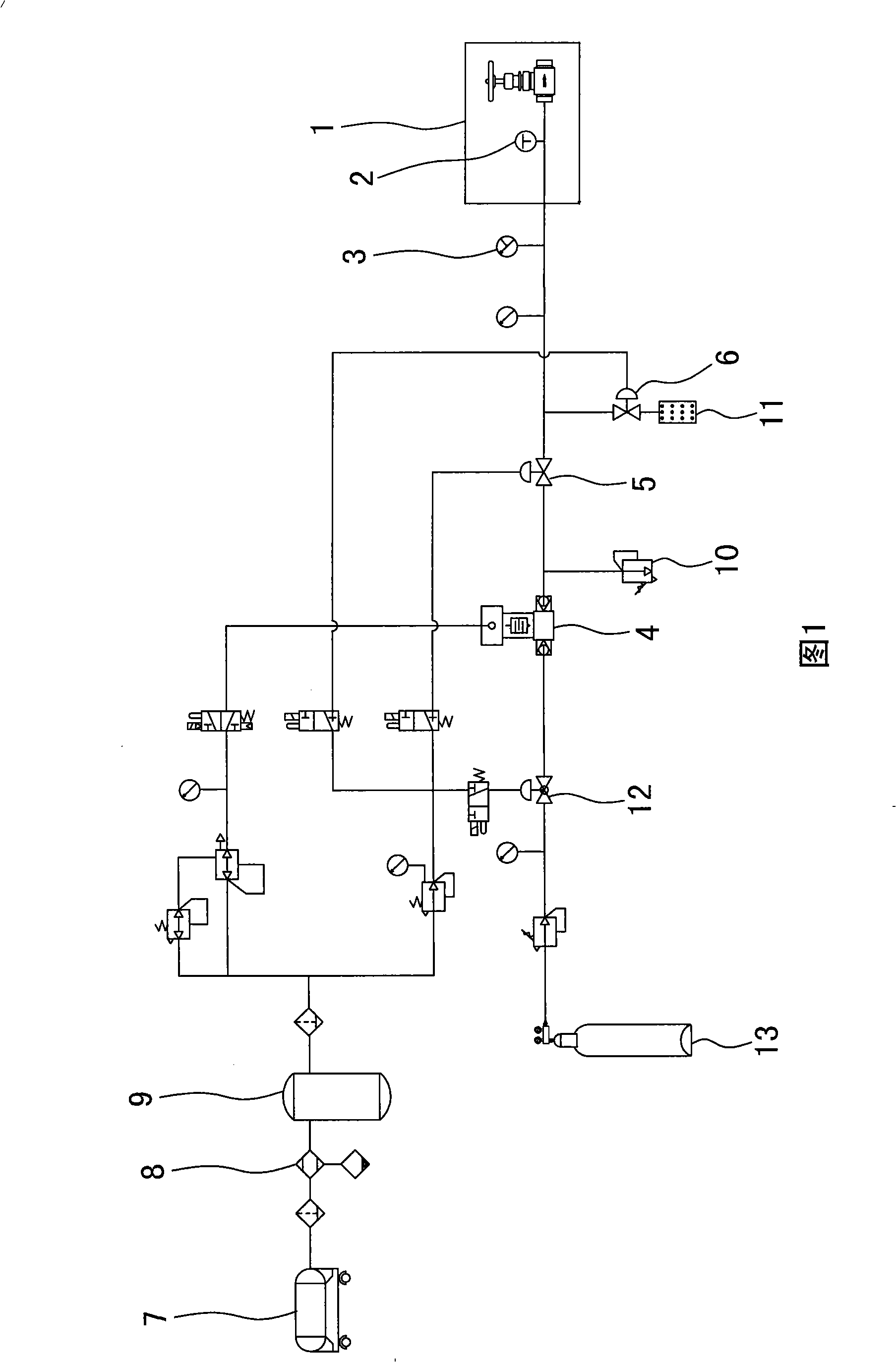
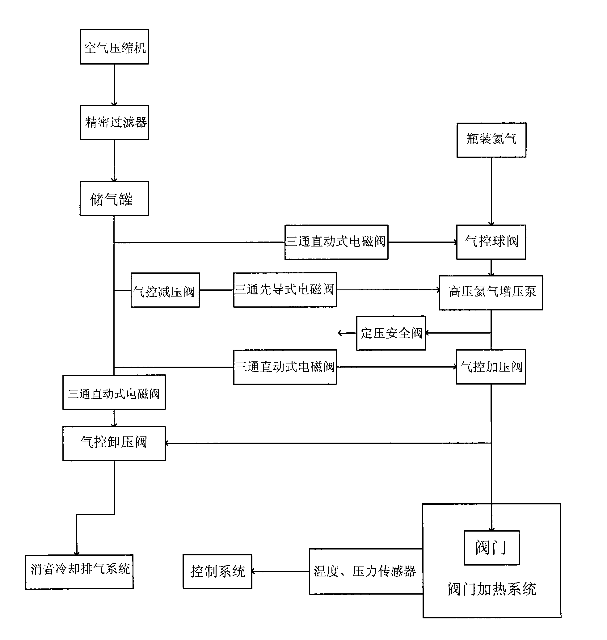
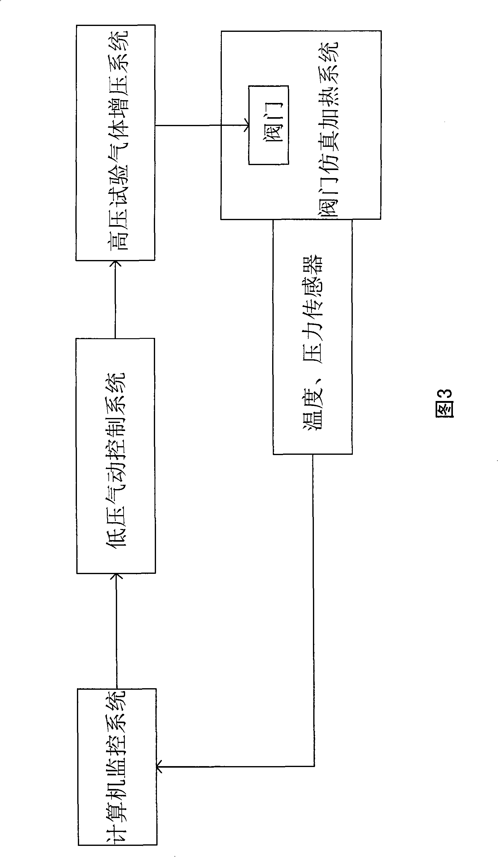
[0029] The device of the present invention is shown in Figures 1 to 3, a pressure test device for valves in a power station, including a valve simulation heating system, a high-pressure test gas pressurization system, a low-pressure pneumatic control system and a computer monitoring system;

[0030] The valve simulation heating system includes a box-type resistance furnace 1, a temperature sensor 2, and a pres...

Embodiment 2

[0045] A shell test method for a valve in a power station. The valve to be tested is connected to the test pipeline, and the connection is set according to the shell test requirements. First, the valve is heated to a set temperature, and the set temperature is 648.0°C, and then filled with helium. , for a shell test where the gauge pressure is not lower than 1.5 times the nominal pressure, and it lasts for 15s under the condition of heat preservation and pressure preservation. If the pressure value drops by more than 0.1MPa, it is judged as unqualified. The specification and model of the valve used is 316NB-GM6, as shown in the following table:

[0046] Set pressure / MPa

[0047] It can be seen that the test method of the present invention uses helium gas as the medium, no comprehensive leakage phenomenon occurs, and the quality status of the valve can be accurately measured.


PUM


Abstract

The invention discloses a method for testing a valve shell of a power station. A valve to be tested is connected with a testing pipeline; connection is set according to the testing requirement of the shell; firstly, the valve is heated to a set temperature which is between 37 and 700 DEG C; secondly, helium gas is filled in the valve; a shell test with gauge pressure not less than 1.5 times of nominal pressure is done; in a heat and pressure retaining state, the test is continued for the set time; and if the pressure value is reduced and exceeds the set standard, the shell is judged to be unqualified. A valve sealing test is similar to the method. The method uses helium gas as a medium and simulates that the high-temperature state of the valve in an actual working environment of the powerstation, thereby accurately measuring the quality situation of the valve and solving the technical problems which people hope to solve all the while and still do not succeed.

Description

technical field [0001] The invention relates to a pressure test method for a valve, in particular to a pressure test method for a high-temperature and high-pressure valve used in a thermal power station. Background technique [0002] Thermal power plants are the most common form of power plants. Special high-temperature and high-pressure valves need to be installed in all process systems of thermal power plants, for example, the process door of the steam system of the boiler system, the instrument door at the front end of the instrument transmitter, and the sampling valve. Various valves of the system, etc. That is to say, the realization of the functions of each process system of the power station is guaranteed by various valves, especially some high-end high-temperature and high-pressure valves, which must be guaranteed to operate well under the conditions of 600°C and 30MPa. If it is turned off, it will affect the economy of unit operation at least, and affect the realiz...

Claims


Application Information

Patent Timeline
Patent Type & Authority Patents(China)
IPC IPC(8): G01M3/28
Inventor 宋建中江华
Owner SUZHOU SAIHUA INSTR CONTROL CO LTD
Why Eureka
Try Eureka