Eureka AIR delivers breakthrough ideas for toughest innovation challenges, trusted by R&D personnel around the world.

A valve thermal test device

A thermal test and valve technology, which is applied in the direction of measuring devices, testing of mechanical components, testing of machine/structural components, etc., to achieve stable temperature and convenient adjustment

Active Publication Date: 2017-02-15
JIANGSU SHENTONG VALVE
View PDF8 Cites 0 Cited by
  • Summary
  • Abstract
  • Description
  • Claims
  • Application Information

AI Technical Summary

Problems solved by technology

[0003] In order to overcome the disadvantage that the existing valve pressure test can only be carried out at normal temperature, the present invention provides a valve thermal test device that can simulate working conditions

Method used


Image

  • A valve thermal test device

Examples


Embodiment Construction

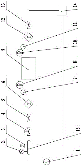
[0014] like figure 1 As shown, a valve thermal test device includes a tested valve 9, a water pump 1, a surge tank 15, a pressure regulating valve 4, a pressure sensor A8, a pressure sensor B10, a shut-off valve A5, a shut-off valve B13 and a water tank 14, and the water pump 1 is connected to the pressure-stabilizing tank 15, and the pressure-regulating valve 4, shut-off valve A5, pressure sensor A8 and the tested valve 9 are sequentially connected behind the pressure-stabilized tank 15, and the pressure sensor B10, shut-off valve B13, The water tank 14, the water tank 14 is connected with the water pump 1, the above-mentioned components are all connected by pipelines, the pressure gauge 2 and the safety valve 3 are installed on the surge tank 15, the thermometer A7 and the pressure sensor are installed between the pressure sensor A8 and the cut-off valve A5 Thermometer B11 is installed between B10 and shut-off valve B13, electric heater A6 is installed on the pipeline betwee...


PUM


Abstract

The invention relates to a valve hot test device. A water pump is connected with a surge tank. A pressure regulating valve, a stop valve A, a pressure sensor A and a tested valve are sequentially connected behind the surge tank. A pressure sensor B, a stop valve B and a water tank are sequentially connected behind the tested valve. The components are all connected through pipelines. A pressure gauge and a safety valve are installed on the surge tank. A temperature gauge A is installed between the pressure sensor A and the stop valve A. A temperature gauge B is arranged between the pressure sensor B and the stop valve B. The pipeline between the temperature gauge A and the stop valve A is provided with an electric heater A and the pipeline between the temperature gauge B and the stop valve B is provided with an electric heater B. The valve hot test device has the advantages that an actual working condition can be simulated so that the quality condition of the valve can be accurately measured under the actual working condition; the valve hot test device is of an open structure so that the valve hot test device can be suitable for valves of different types and different specifications; temperature is automatically controlled through a thermocouple thermodetector, temperature is stable, and adjustment is convenient.

Description

technical field [0001] The invention relates to a test device, in particular to a valve thermal state test device. Background technique [0002] The existing valve detection method is to carry out a pressure test, that is, mainly a shell strength test and a tightness test of the valve. For a long time, the pressure test methods at home and abroad have been carried out at room temperature, which is very different from the temperature under actual working conditions, so it is impossible to accurately measure the quality of the valve under actual working conditions, and the valve is under high temperature and high pressure. Its material is prone to creep, which will cause some valves that pass the normal temperature test to leak when they are used in the actual working environment. Contents of the invention [0003] In order to overcome the disadvantage that the existing valve pressure test can only be carried out at normal temperature, the invention provides a valve thermal...

Claims


Application Information

Patent Timeline
Patent Type & Authority Patents(China)
IPC IPC(8): G01M13/00G01M3/28
Inventor 张逸芳龚燕华陆平
Owner JIANGSU SHENTONG VALVE
Why Eureka
Eureka Blog
Learn More