

Sulfur hexafluoride gas sample collection apparatus
A technology for collecting sulfur hexafluoride gas and samples, which is applied in the direction of sampling devices, etc., can solve the problems of cumbersome sampling process, it is difficult to ensure that the sampling container is cleaned and completely isolated, and achieve the effect of ensuring repeatability
Inactive Publication Date: 2009-07-08
STATE GRID CHONGQING ELECTRIC POWER CO ELECTRIC POWER RES INST
View PDF0 Cites 32 Cited by
- Summary
- Abstract
- Description
- Claims
- Application Information
AI Technical Summary
Problems solved by technology
[0007] Since the sampling bag does not have a convenient vacuum valve and pressure display device, it is generally sampled by flushing. First, the air in the sampling bag is removed, and after the sampling bag is connected to the equipment, the sample gas is filled, the valve of the equipment is closed, and the sample gas is discharged. Exclude, so repeat 3 times, and then collect samples, the sampling process is cumbersome, and it is difficult to ensure that the sampling container is cleaned and completely isolated from the outside world
Method used
View moreImage
Smart ImageViewing Examples

Examples
Embodiment Construction
[0022] The present invention will be described in further detail below in conjunction with the accompanying drawings.
Login to View More PUM
 Abstract
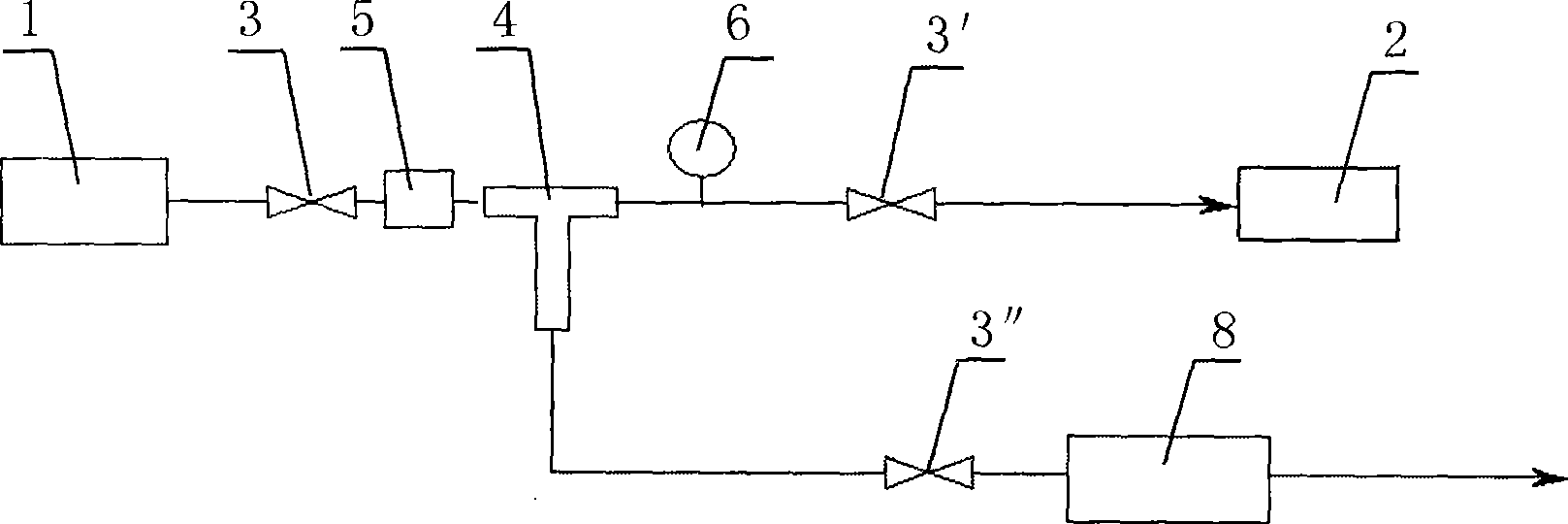
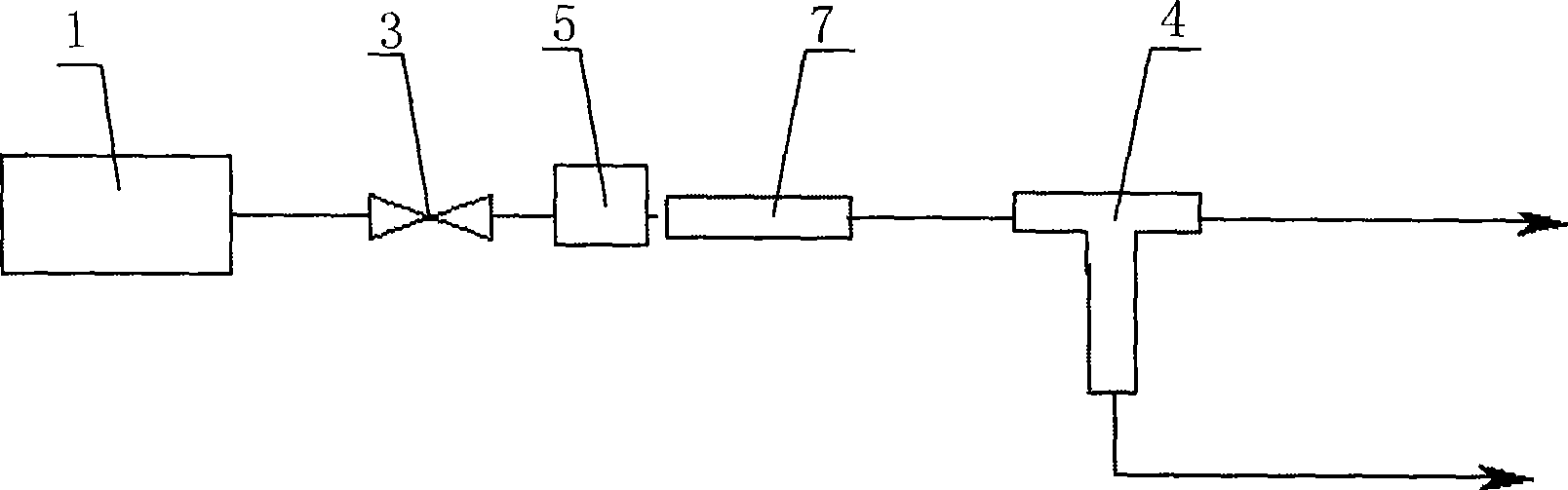
The invention discloses a sulfur hexafluoride gas sample collecting device. The device is provided with a gas picking joint of a fast-inserted pipe, and the appearance of the device is a case body structure provided with an upturning cover; the relative buckling faces of a case body and the upturning cover are provided with a control panel and a display screen respectively; the periphery of the case body is provided with a fast-inserted gas path interface and a power interface; and the case body is provided with a triple valve, an SF6 flow rate electronic controller, a minitype vacuum pump, an electromagnetic valve and an integrated circuit control system inside. The collecting device has the advantages of portable design, full closed sampling, and sample undistortionless, and has the function of controlling the flow rate to precisely set the flow rate so as to be convenient to connect an SF6 gas detector with higher requirements on the flow rate precision. The device completely meets the electric power industry standard of an SF6 gas sampling method for electrical equipment.
Description
technical field [0001] This invention relates to gas sample collection equipment for the power industry, specifically SF 6 (Sulfur hexafluoride) gas sample collection device for electrical equipment. Background technique [0002] With the development of the power industry, SF 6 The number of electrical equipment installed and put into operation continues to increase, and the SF 6 The supervision of gas is becoming more and more important. The samples taken must be able to represent the characteristics of most gases in the equipment body, and must be guaranteed not to be polluted by external gases. [0003] There are two main sampling methods: [0004] 1) Sampling cylinder [0005] When sampling with a sampling cylinder, the cylinder must first be evacuated. Due to the large vacuum pump, this process is generally operated in a laboratory. There is a three-way valve on the top of the sampling cylinder. After the vacuum pump is connected to the sampling cylinder, turn the t...
Claims
Login to View More Application Information
Patent Timeline
 IPC IPC(8): G01N1/24
Inventor姚强李毅刘永
OwnerSTATE GRID CHONGQING ELECTRIC POWER CO ELECTRIC POWER RES INST