Infrared touch positioning device

A positioning device, infrared touch technology, applied in the direction of instrument, electrical digital data processing, data processing input/output process, etc., can solve the problems of high cost, complex circuit structure, increase the difficulty of production process, etc., to reduce the number of use , the circuit structure is simple, the effect of reducing cost

Inactive Publication Date: 2009-07-08
GUANGDONG VTRON TECH CO LTD
View PDF1 Cites 16 Cited by
  • Summary
  • Abstract
  • Description
  • Claims
  • Application Information

AI Technical Summary

Problems solved by technology

[0003] Although the infrared positioning technology has many advantages, but because the infrared emitting tube has a fixed emission angle, the infrared emitting tubes will interfere with each other. The infrared positioning touch device of the prior art adds a light guide hole on the edge of the screen to improve the interference. , the light guide hole is a shell integrated with the screen frame. Aligning the infrared emitting tube and the receiving tube with the light guide hole can suppress the interference between the infrared emitting tubes, but in the process, the infrared emitting tube and the receivin

Method used


Image

  • Infrared touch positioning device
  • Infrared touch positioning device
  • Infrared touch positioning device

Examples


Embodiment 1

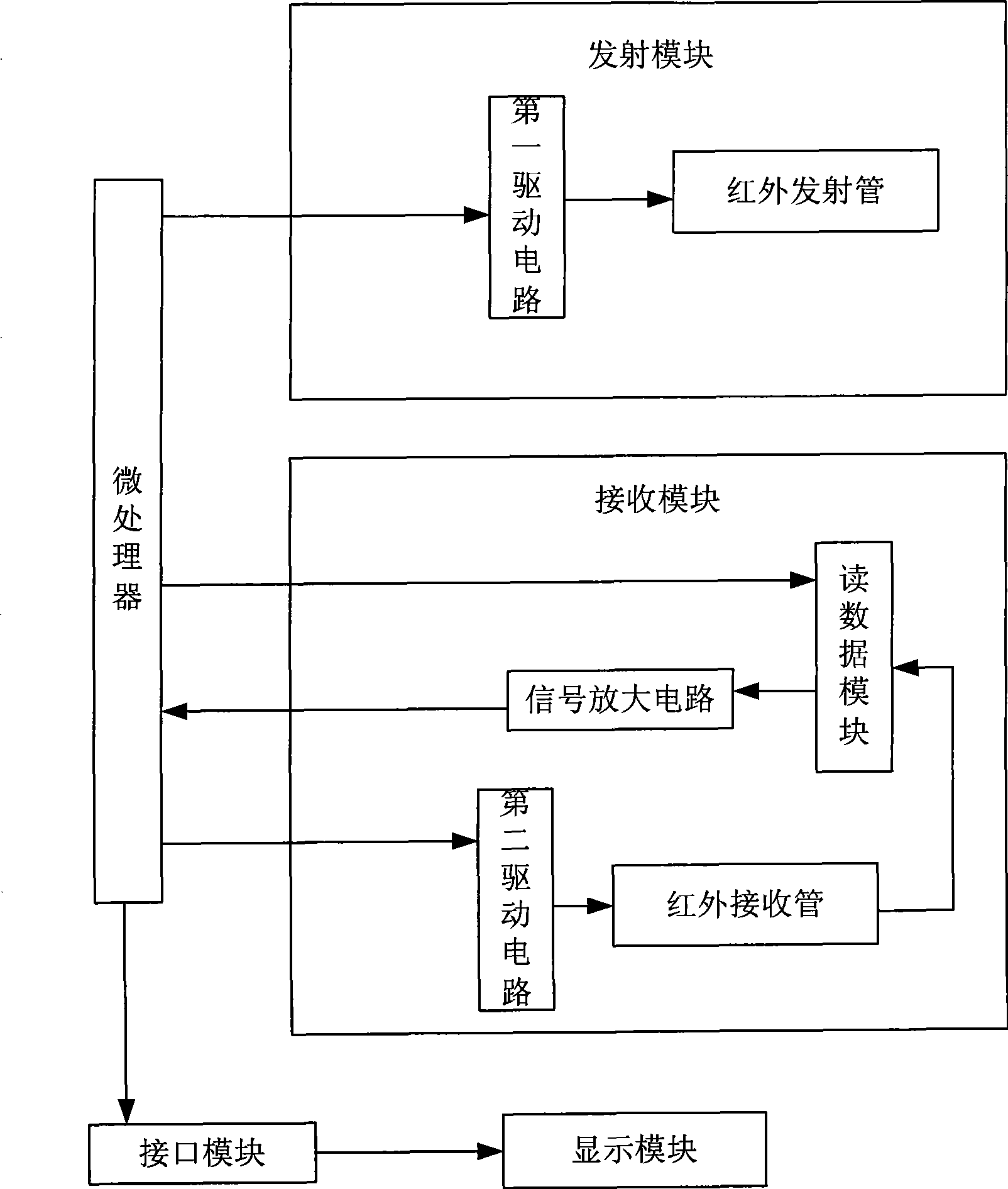
[0020] In this embodiment, the infrared touch positioning device of the present invention includes, such as figure 1 , including a microprocessor, at least one group of relatively distributed transmitting modules and receiving modules (a group of transmitting modules and receiving modules are shown in the figure), each group of transmitting modules and receiving modules is installed on the corresponding two sides of the touch screen , the transmitting module includes a first driving circuit and each infrared emitting tube; the receiving module includes a second driving circuit, each infrared receiving tube, a data reading module and a signal amplification circuit;

[0021] The I / O port of the microprocessor is respectively connected to the input end of the first driving circuit, the control end of the data reading module and the input end of the second driving circuit, and each output end of the first driving circuit is connected to the input end of the second driving circuit. ...

Embodiment 2

[0027] This embodiment is a specific application example. In this embodiment, the infrared touch positioning device of the present invention includes two groups of transmitting modules and receiving modules, wherein one group of transmitting modules and receiving modules is installed on the left and right of the touch screen, and another group of transmitting modules and receiving modules is installed on the Touch the top and bottom of the screen. Such as Figure 5, the upper receiving module and the left receiving module are located at the top and left of the touch screen, and the lower transmitting module and the right transmitting module are located at the bottom and right of the touch screen. The control ports of the microprocessor are respectively connected with the upper receiving module, the left receiving module, the lower transmitting module and the right transmitting module. The output ends of the upper receiving module and the left receiving module are output to t...


PUM


Abstract

The invention discloses an infrared-touch positioning device. The device comprises a microprocessor, at least one set of an emission module and an receiving module which are oppositely distributed, and the emission module comprises a first driving circuit and a plurality of infrared emitting tubes; the receiving module comprises a second driving circuit, a plurality of infrared receiving tubes, a data reading module and a signal amplifying circuit; the microprocessor controls the gating of each infrared emitting tube and each infrared receiving tube in sequence by controlling the first driving circuit and the second driving circuit, and reads induction signals of the infrared emitting tube by controlling the data reading module; the induction signals are output to the microprocessor after being amplified by the signal amplifying circuit; the microprocessor converts the induction signals into digital signals, converts the digital signals into the corresponding coordinate information and outputs to a display module for being displayed through an interface module. The infrared-touch positioning device of the invention has the advantages that the cost of the whole infrared-touch positioning device is lowered because just one microprocessor is used, the cost of the whole infrared-touch positioning device is reduced, the circuit structure is simple and the anti-interference performance is strong.

Description

technical field [0001] The invention relates to electronic touch technology, in particular to an infrared touch positioning device. Background technique [0002] Electronic touch technology provides great convenience for human-computer interaction, and also provides a variety of technical solutions, and the performance and reliability are constantly improving. At present, there are two common electronic touch technologies in the market: one is the passive method, which uses resistance, capacitance, and infrared scanning technology, and is characterized by touch positioning without a specially made electronic pen; the other is the active method. , such as electromagnetic positioning and ultrasonic positioning, this method requires a specially made electronic pen to achieve touch positioning. Once the pen is lost or damaged, the entire positioning system will not work. With the continuous development of electronic touch technology, infrared scanning positioning technology has...

Claims


Application Information

Patent Timeline
IPC IPC(8): G06F3/042
Inventor 周春景钟杰婷
Owner GUANGDONG VTRON TECH CO LTD
Why Eureka
Try Eureka