Power management system

A technology of power management system and system power supply, which is applied in the direction of control/regulation system, current collector, electric vehicle, etc., and can solve problems such as system malfunction, input power cannot be maintained, and input power voltage signal is lowered

Active Publication Date: 2010-12-29
ALLWINNER TECH CO LTD
View PDF0 Cites 2 Cited by
  • Summary
  • Abstract
  • Description
  • Claims
  • Application Information

AI Technical Summary

Problems solved by technology

If any one of the system consumption current, charging current and the sum of the two exceeds the driving capability of the input power supply, the voltage signal of the input power supply will not be maintained, resulting in the system not working properly
[0006] In practical applications, more and more AC adapter plugs are also made into USB plugs. Since the electronic device itself does not judge the driving capacity of the input power, if the electronic device uses a drive capacity that is less than the maximum power consumption of the electronic device adapter, it may also drag down the voltage signal of the input power supply, which will cause the system to not work properly

Method used


Image

  • Power management system
  • Power management system
  • Power management system

Examples


Embodiment 1

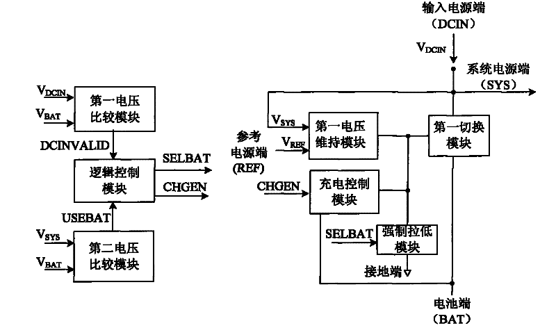
[0023] The power management system proposed in this embodiment includes: an input power supply terminal, a battery terminal, a system power supply terminal, a ground terminal, a reference power supply terminal, a first voltage maintaining module, a first switching module, a charging control module, a forced pull-down module, a second A voltage comparison module, a second voltage comparison module and a logic control module.

[0024] Wherein, for the convenience of description, the input power terminal is called DCIN, the battery terminal is called BAT, the system power terminal is called SYS, and the reference power terminal is called REF. Correspondingly, the input power terminal voltage signal is called V DCIN , the battery terminal voltage signal is called V BAT , the system power supply terminal voltage signal is called V SYS , the reference power supply terminal voltage signal is called V REF .

[0025] In this power management system, the first voltage maintenance mo...

Embodiment 2

[0036] In the prior art, when the system consumes the current signal, the charging current signal and the sum of the two, any one of these is greater than the current signal provided by the input power supply, the voltage signal of the input power supply terminal will not be maintained, and if this input power comes from USB port, it will violate the USB specification, resulting in USB connection interruption.

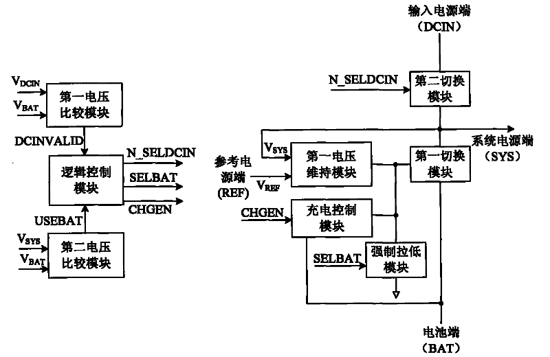
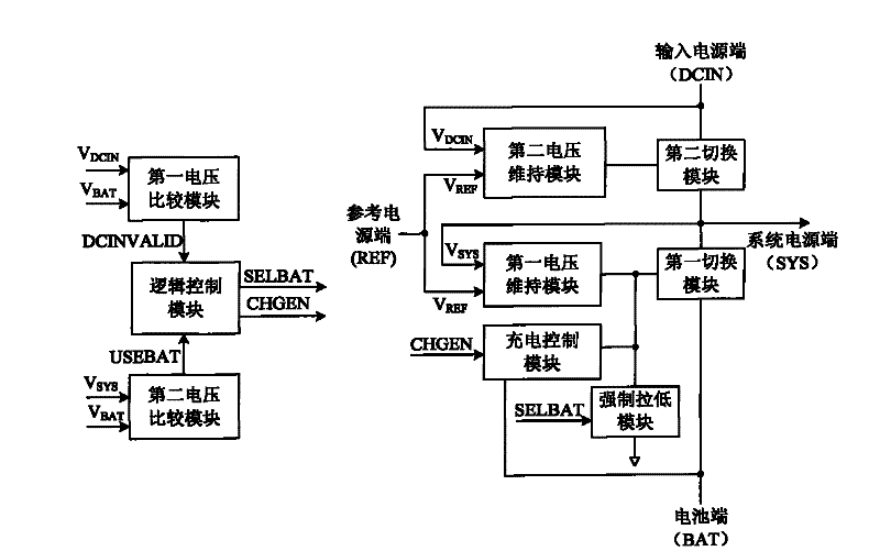
[0037] The system power terminal receives the voltage signal of the input power terminal, and the connection relationship includes two ways:

[0038] The first way: on the basis of the power management system proposed in Embodiment 1, a second switching module is also included. The input power supply terminal, the second switching module and the system power supply terminal are sequentially connected; the logic control module outputs a fourth control signal to the second switching module according to the received power supply connection signal, such as figure 2 as sh...

Embodiment 3

[0047] As a further improvement of Embodiment 1 above, the first differential amplifier further includes an enabling terminal, which receives the enabling signal generated by the logic control module according to the received power supply connection signal and battery connection signal.

[0048] Figure 7 It is a schematic diagram of a specific implementation of an integrated circuit including the last stage circuit of the first voltage maintenance module, the last stage circuit of the charging control module, the first switching module and the forced pull-down module. The integrated circuit includes a current source, a second Three PMOS transistors, a fourth PMOS transistor, a first PMOS transistor and an NMOS transistor. Wherein, the third PMOS transistor represents the last stage output circuit of the first voltage maintaining module, and the fourth PMOS transistor represents the last stage output circuit of the charging control module. In this embodiment, the current supp...


PUM


Abstract

The invention discloses a power management system. A reference power end, a first voltage maintenance module, a first switching module, a charging control module, a forced pull-low module, a first voltage comparison module, a second voltage comparison module and a logic control module are additionally arranged on the basis of a common power management system including an input power terminal, a battery terminal, a system power terminal and a grounding terminal. The provided power management system can automatically reduce the charging current signal until no current signal exists under the condition that the system cannot normally work due to insufficient driving power of the input power supply; and if the input power supply cannot supply the sufficient power for the system, the battery is enabled at the same time, so that the battery and the input power supply simultaneously supply power for the system to ensure the normal work of the system.

Description

technical field [0001] The invention relates to the field of power management, in particular to a power management system. Background technique [0002] Most of the power supply components of portable electronic devices are as follows: a battery can be installed to directly draw power from the battery to work, or an interface connector capable of supplying power such as an AC adapter or a USB interface connector can be installed to draw power to work. [0003] Due to factors such as economy and environmental protection, most of the batteries used in fashionable portable electronic devices are rechargeable batteries. Among them, because they can provide a larger discharge current and have almost no memory effect, compared with traditional rechargeable batteries such as nickel-cadmium batteries and nickel-metal hydride batteries, lithium-ion or lithium polymer rechargeable batteries are more and more commonly used. [0004] In order to keep the power of the battery as last as...

Claims


Application Information

Patent Timeline
Patent Type & Authority Patents(China)
IPC IPC(8): H02J7/00G05F1/10
Inventor 丁然邓琴吴建舟
Owner ALLWINNER TECH CO LTD
Why Eureka
Try Eureka