liquid gas buffer

A liquid-gas buffer and liquid chamber technology, which is applied in the direction of gas-liquid shock absorbers, shock absorbers, shock absorbers, etc., can solve the problems of low group resistance, limited cushioning performance, and low static capacity, so as to improve the service life , Improve the working conditions, and the effect of small change in the volume of the oil chamber

Active Publication Date: 2021-04-20
CRRC QINGDAO SIFANG ROLLING STOCK RES INST
View PDF5 Cites 0 Cited by
  • Summary
  • Abstract
  • Description
  • Claims
  • Application Information

AI Technical Summary

Problems solved by technology

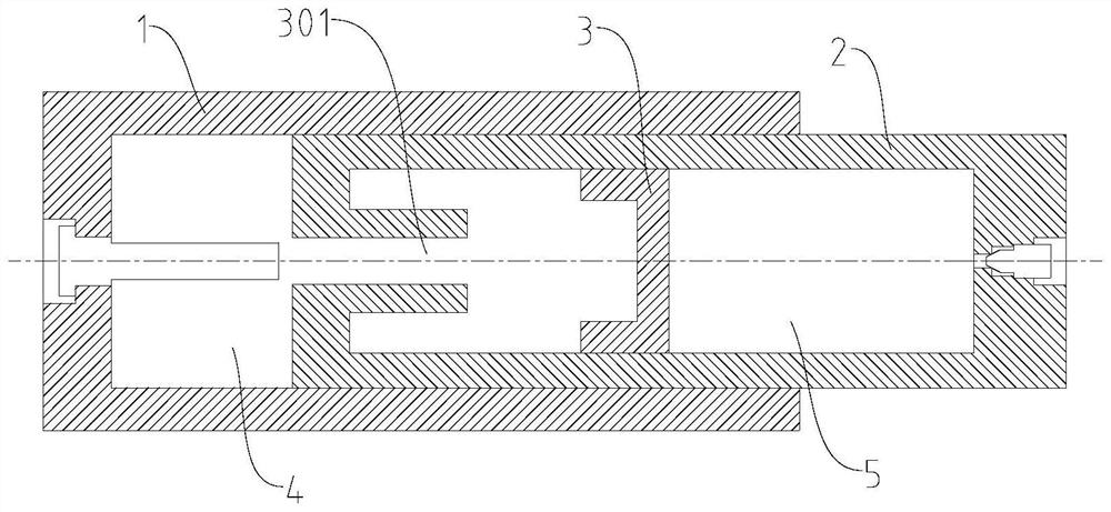
[0004] The object of the present invention is to provide a liquid-gas buffer with compact structure and high resistance for the problem of low resistance and low static capacity of the liquid-gas buffer group in the prior art, resulting in limited buffering performance.

Method used


Image

  • liquid gas buffer
  • liquid gas buffer
  • liquid gas buffer

Examples


Embodiment Construction

[0040] In order to make the technical problems, technical solutions and beneficial effects to be solved by the present invention clearer, the present invention will be further described in detail below in conjunction with the accompanying drawings and embodiments. It should be understood that the specific embodiments described here are only used to explain the present invention, not to limit the present invention.

[0041] It should be noted that when an element is referred to as being “disposed on” or “connected to” another element, it can be directly on the other element or indirectly on the other element. When an element is referred to as being "connected to" another element, it can be directly connected to the other element or indirectly connected to the other element.

[0042] It should be understood that the orientation or positional relationship indicated by the terms "upper", "lower", "vertical", "top", "bottom", "inner", "outer" etc. is based on the orientation or pos...


PUM


Abstract

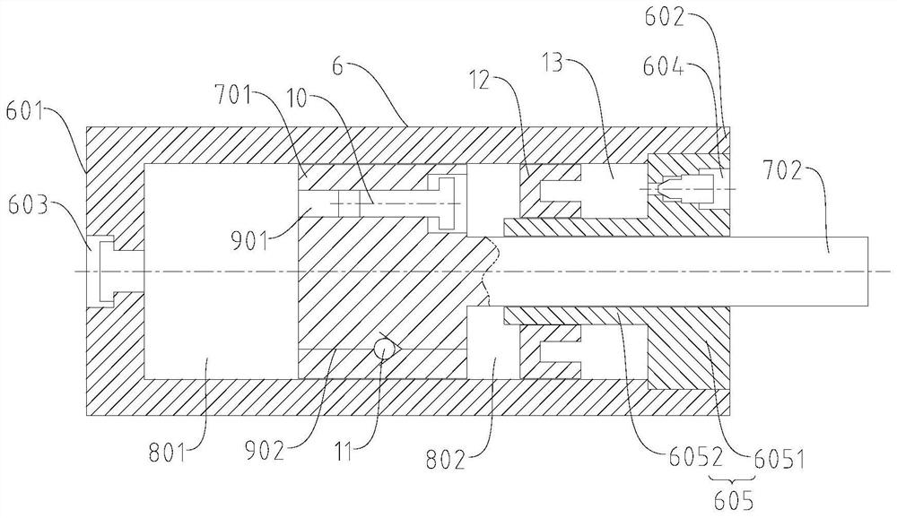
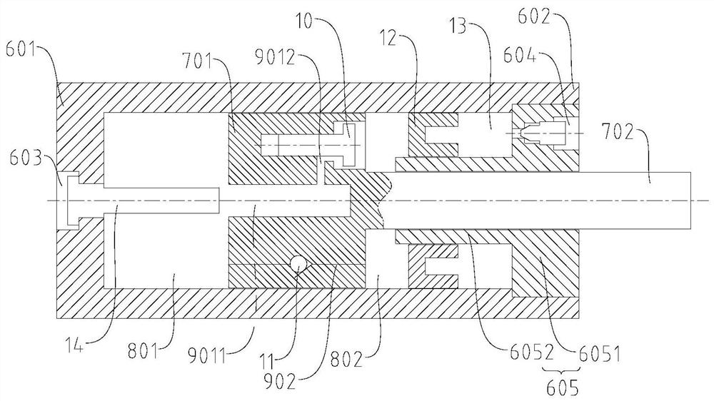
The invention provides a liquid-gas buffer, comprising: a cylinder body; a first piston assembly: including a piston head and a force transmission rod, the piston head is arranged in the cylinder body, and the cylinder body is divided into a first liquid cavity and a second A liquid chamber, the force transmission rod extends out of the cylinder; the piston head is provided with a first fluid channel and a second fluid channel communicating with the first liquid chamber and the second liquid chamber; the first fluid channel is provided with The first switching element is configured to open when the pressure in the first liquid chamber is greater than the pressure in the second liquid chamber; the second fluid channel is provided with a second switching element configured to open when the pressure in the second liquid chamber is greater than the pressure in the first liquid chamber. When the liquid chamber is under pressure, it is opened; the second piston assembly is arranged around the force transmission rod, and the second liquid chamber is formed between the piston head and the cylinder port to form an air chamber. The piston assembly of the liquid-gas buffer adopts a partly built-in and partly externally designed structure, which is used as a liquid cavity separation component and a force transmission component to make the buffer structure more compact.

Description

technical field [0001] The invention relates to the technical field of coupler buffering, in particular to a liquid-gas buffer. Background technique [0002] The interior of the liquid-gas buffer is mainly composed of two chambers, oil and gas, which are separated by a liquid-gas separation piston. The oil cavity is filled with hydraulic oil, and a throttling hole with a certain damping coefficient is arranged inside. The air cavity is filled with an inert gas with a certain pressure. When the buffer is under pressure, on the one hand, the hydraulic oil flows through the throttling pores and rubs against the metal wall to generate heat, thereby dissipating most of the external compression kinetic energy; on the other hand, the inert gas is compressed, compressing a small part of the external The kinetic energy is converted into the compression potential energy of the gas, which powers the subsequent recovery of the buffer. [0003] The structure of the traditional structu...

Claims


Application Information

Patent Timeline
Patent Type & Authority Patents(China)
IPC IPC(8): F16F9/06F16F9/32F16F9/34
CPCF16F9/061F16F9/067F16F9/3207F16F9/3214F16F9/3221F16F9/3405
Inventor 毛从强李辛刘辉齐亚文郝博于正庭高晗谢想
Owner CRRC QINGDAO SIFANG ROLLING STOCK RES INST
Why Eureka
Try Eureka