Combustion engine technology

a technology of combustion engine and combustion chamber, which is applied in the direction of machines/engines, combustion air/fuel air treatment, electric control, etc., can solve the problems of high pressure pump, heavy and costly components, and high noise of pump and drive, and achieves excessive noise and structural stress, vibration and harshness, and high nois

Inactive Publication Date: 2008-11-06
DELPHI TECH INC
View PDF5 Cites 19 Cited by
  • Summary
  • Abstract
  • Description
  • Claims
  • Application Information

AI Technical Summary

Benefits of technology

[0013]It is beneficial for the piston to be at least partially filled with a medium for aiding heat transfer away from a surface of the piston that is exposed to gases within the combustion chamber to aid heat transfer away from the lower face of the piston to the cylinder head.

Problems solved by technology

The high pressure pump is a complex, heavy and costly component, and although common rail systems provide benefits over more traditional fuel injection systems (e.g. distributor pumps, unit pumps), there are significant implications on engine design with respect to the location of the high pressure pump and its drive arrangement.
In particular, the drive torque signature can include “spikes” which make the pump and its drive a leading source of undesirable noise, vibration and harshness.
The various advanced combustion modes may be characterised by, among other things, the lack of a positive initiator for the start of combustion, the requirement for relatively high levels of dilution of the charge with exhaust gas and the undesirable generation of high rates of cylinder pressure rise (dp / dt) resulting in excessive noise and structural stress.
Although advanced combustion modes provide benefits for efficiency and emissions, the aforementioned characteristics in particular present problems for which solutions are sought.

Method used


Image

  • Combustion engine technology
  • Combustion engine technology
  • Combustion engine technology

Examples


Embodiment Construction

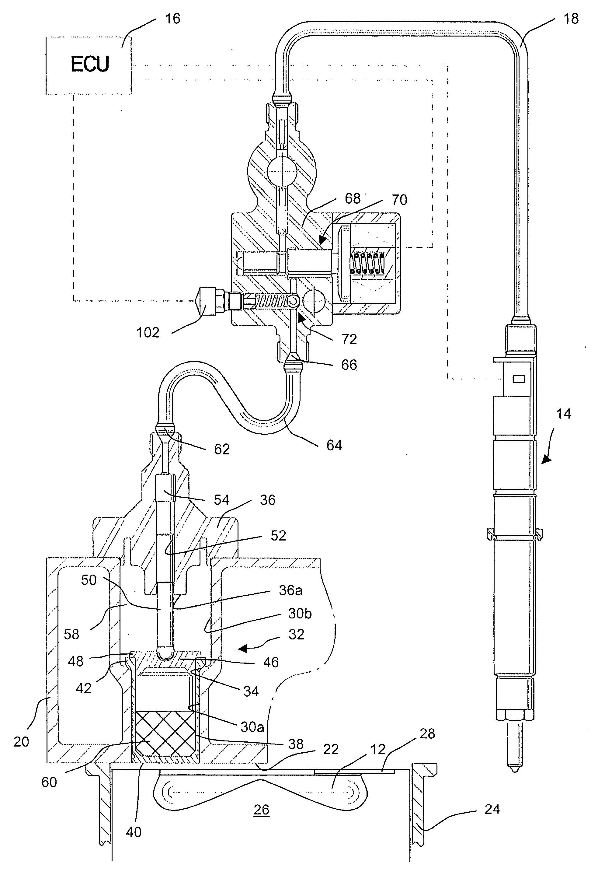
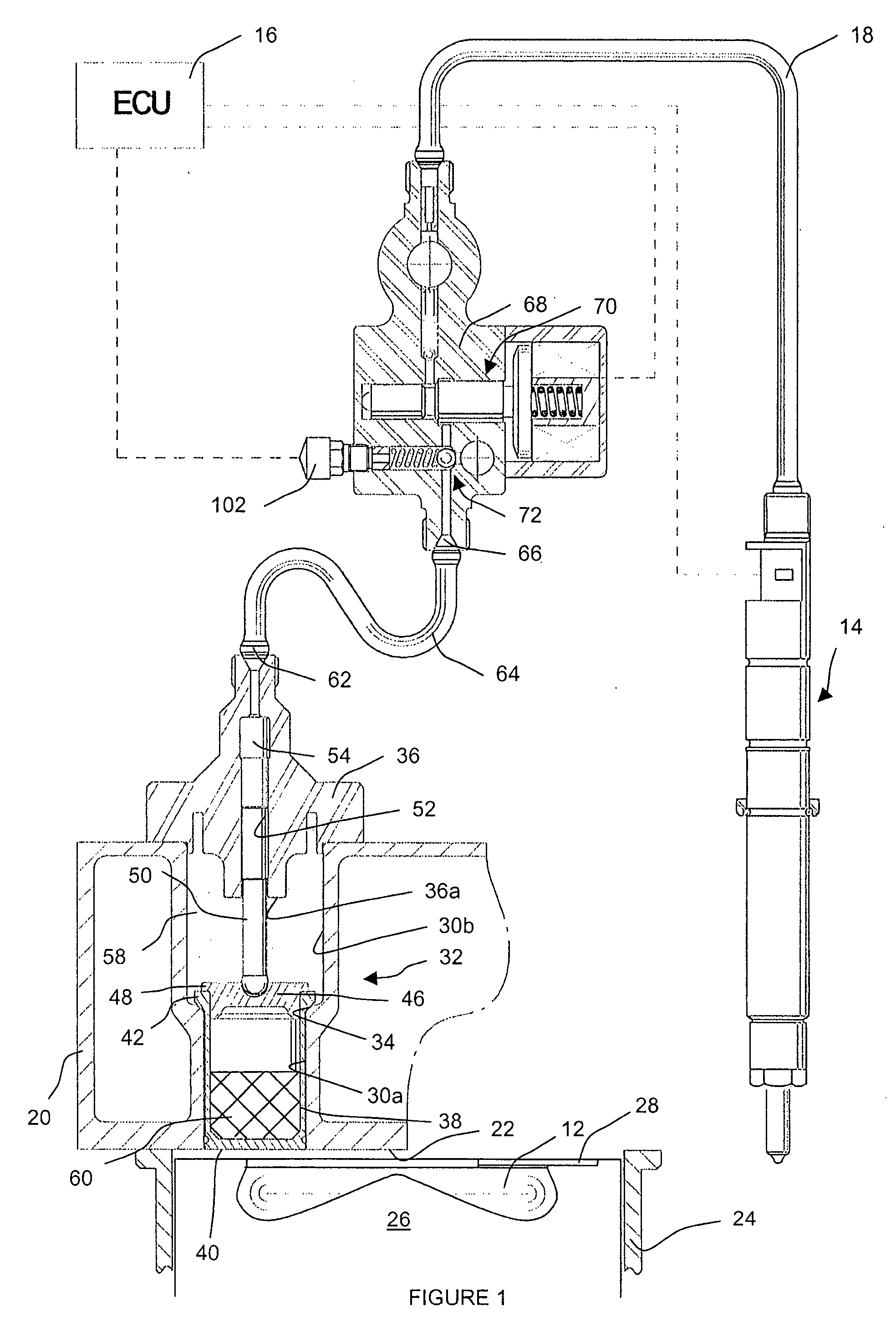
[0038]Referring to FIG. 1, an engine cylinder for an internal combustion engine of the compression ignition (diesel) type defines a combustion chamber 12 into which combustible fuel is injected. In general, the engine is provided with a plurality of cylinders, but for simplicity only one of the cylinders will be described here. The combustion chamber 12 has an associated fuel injector 14 which is arranged to inject fuel at relatively high pressure into the combustion chamber 12 under the control of an Engine Control Unit (ECU) 16. The injector 14 receives pressurised fuel for injection through a supply passage 18.

[0039]The engine cylinder has a cylinder head 20 which defines an upper ceiling of the combustion chamber 12, typically referred to as the fire deck 22. A cylinder piston 26 is driven, in use, by a crank shaft of the engine within a cylinder sleeve 24. The cylinder piston 26 is provided with a recess or crown in its upper surface to define a piston bowl which forms a lower ...


PUM


Abstract

A fuel system for use in a combustion chamber of a compression ignition internal combustion engine comprises a pump arrangement having a pump chamber for fluid and a piston which is movable outwardly from the combustion chamber in response to pressure generated within the combustion chamber as a result of combustion so as to pressurise fluid within the pump chamber. The system also includes a control valve assembly for controlling the supply of fluid that is pressurised within the pump chamber to an accumulator volume. In one particular aspect, the invention provides a fuel system for use in an engine having at least two engine cylinders, comprising a first pump arrangement associated with one of the engine cylinders and a second pump arrangement associated with the other of the engine cylinders, each of the first and second pump arrangements having a pump chamber for fluid and a piston which is movable outwardly from the combustion chamber in response to pressure generated within the combustion chamber as a result of combustion so as to pressurise fuel within the pump chamber. At least one control valve assembly controls the supply of fluid that is pressurised within the pump chamber of at least one of the pump arrangements to an accumulator volume.

Description

TECHNICAL FIELD[0001]The invention considers improvements relating to compression ignition (diesel) internal combustion engine technology. In particular, the invention relates to an improved cylinder-pressure operated fuel pump for a common rail diesel fuel injection system.BACKGROUND TO THE INVENTION[0002]Increasingly, fuel injection systems of the common rail type are specified for new diesel engines. In such systems a multi-piston pump raises fuel pressure to a level that is suitable for injection directly into the engine combustion chamber. Typically, the system includes a high pressure pump having a cam drive arrangement, an accumulator volume or rail, one injector per engine cylinder and an electronic control unit (ECU) for controlling injection timing and other parameters. The high pressure pump is a complex, heavy and costly component, and although common rail systems provide benefits over more traditional fuel injection systems (e.g. distributor pumps, unit pumps), there ar...

Claims


Application Information

Patent Timeline
Patent Type & Authority Applications(United States)
IPC IPC(8): F02M61/04
CPCF02D15/04F02D41/3035F02M49/02F02M63/027F02M2700/1341Y02T10/12
Inventor DINGLE, PHILIP J. G.
Owner DELPHI TECH INC
Why Eureka
Try Eureka