Heat radiating device and manufacturing process thereof

A technology of a heat dissipation device and a manufacturing method, which is applied to indirect heat exchangers, lighting and heating equipment, cooling/ventilation/heating renovation, etc. The effect of saving processing time and cost, simple and reliable manufacturing process, and saving installation space

Active Publication Date: 2009-07-08
BEIJING AVC TECH RES CENT
View PDF2 Cites 44 Cited by
  • Summary
  • Abstract
  • Description
  • Claims
  • Application Information

AI Technical Summary

Problems solved by technology

Although these methods can solve the heat dissipation problem of high-power devices to a certain extent, there are still the following disadvantages: (1) fan + heat sink, in order to enhance the heat dissipation capacity of the heat dissipation device, only by increasing the area of ​​the heat dissipation fins and Increase the fan speed, resulting in loud noise, large and heavy cooling device, which is not conducive to installation and will generate great pressure on electronic devices; (2) fan + heat pipe + radiator, although it can solve the shortcomings in method 1 , but it will increase the complexity of the mechanism itself, the design and installation of heat pipes are often limited by the actual structure, and under the action of limited heat pipes, its heat dissipation capacity is still limited; 3) Liquid cooling technology surpasses the above two in terms of performance This way, and the potential of liquid cooling heat dissipation technology is very high. If a small liquid cooling heat dissipation device is optimized in performance, it can already dissipate 1000 watts of heat under the premise of controlling noise (the overall thermal resistance of the liquid cooling radiator can be as low as 0.12℃ / W or less)
[0006] Since the shape of an ordinary electronic chip is basically a square (cube or cuboid), the cylindrical evaporator is not conducive to contact with the flat surface of the chip due to the diameter of the cylinder, while the disc-shaped flat plate is due to the complicated manufacturing process of the evaporator, and in It will take up extra space when installed. As of now, the heat dissipation performance of the loop heat pipe using the flat plate evaporator made by micromachining technology has not yet reached the requirements of commercial use.

Method used


Image

  • Heat radiating device and manufacturing process thereof
  • Heat radiating device and manufacturing process thereof
  • Heat radiating device and manufacturing process thereof

Examples


Embodiment Construction

[0046] see figure 2 As shown, a heat dissipation device of the present invention is a schematic structural diagram of a loop heat pipe heat dissipation device of a flat plate evaporator. The embodiment of the heat dissipation device of the present invention mainly includes a flat plate evaporator 1, a steam pipeline 2, a liquid Pipeline 3, a condenser 4 and / or a fan 5 that provides air to flow through the condenser 4, the fan 5 is installed on one side of the condenser 4. The shape of the flat plate evaporator 1 is a rectangle or a polygon or a geometry.

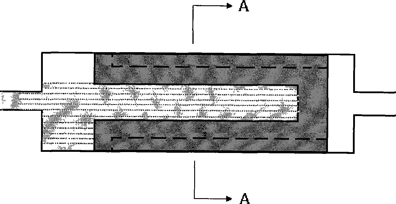
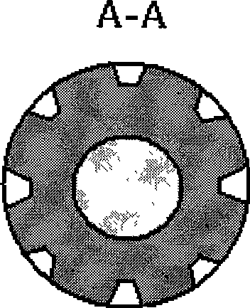
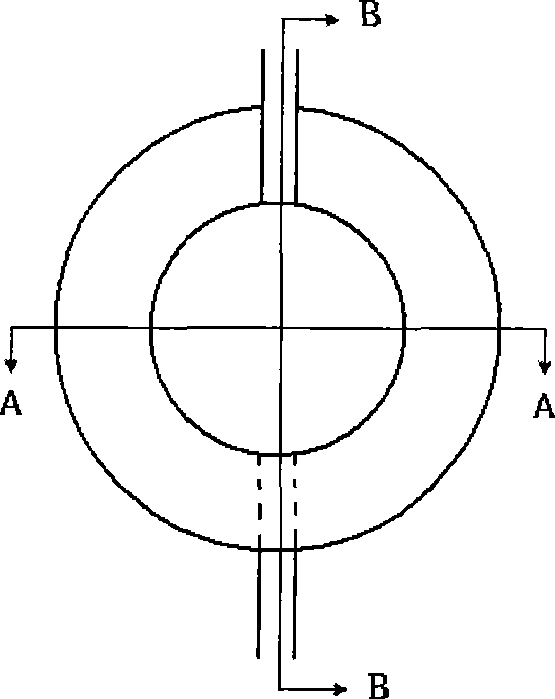
[0047] see Figure 3A and Figure 3B and Figure 7 As shown, the flat panel evaporator 1 has a main body, and the main body system includes a bottom plate 11 , a porous material 12 and an upper cover 13 . The porous material is arranged in the accommodating space of the main body. An interface is provided on both sides of the main body, and the interfaces are steam interface and liquid interface respectively. like F...


PUM


Abstract

The invention discloses a heating abstractor, which comprises a plate evaporator, a steam piping, a liquid line and a condenser. Wherein, the plate evaporator comprises a body composed of a soleplate, multi-pore material and a top cover, and the multi-pore material is provided and tied with a passage for steam to excrete and is arranged on the soleplate; the top cover and the soleplate are connected; two sides of the top cover are respectively provided with a steam interface and a liquid interface; two ends of the steam piping are respectively communicated with the steam interface and the liquid interface of the plate evaporator and two sides of the condenser. The heating abstractor has the advantage of effectively and completely jointing the evaporator and an electronic chip, saving installation space, lowering resistance of heat transfer; besides, the craft is simple and reliable, the cost is low; not only heat dissipation of a computer chip is applicable, but also an application to a lighting emitting diode lighting equipment, chip cooling in communication industry and cooling of high-energy heating components inside of military, medical and aerospace equipment is suitable.

Description

technical field [0001] The invention relates to a heat dissipation device in the field of electronic products, in particular to a structure and a processing method of a heat dissipation device related to a loop heat pipe. Background technique [0002] The cooling of high-power electronic chips is a very important technical link in electronics, computers, communications and optoelectronic equipment. At present, the commonly used methods for heat dissipation of high-power electronic devices in the market include the following: (1) fan + radiator; (2) fan + heat pipe + radiator; (3) fan + liquid cooling technology. Although these methods can solve the heat dissipation problem of high-power devices to a certain extent, there are still the following disadvantages: (1) fan + heat sink, in order to enhance the heat dissipation capacity of the heat dissipation device, only by increasing the area of ​​the heat dissipation fins and Increase the fan speed, resulting in loud noise, lar...

Claims


Application Information

Patent Timeline
Patent Type & Authority Applications(China)
IPC IPC(8): H05K7/20H01L23/427B23P15/26B22F3/11B22F7/00
CPCH01L23/467H01L2924/0002F28D15/046H01L23/427F28D15/0266Y10T29/49353H01L2924/00
Inventor 李骥
Owner BEIJING AVC TECH RES CENT
Why Eureka
Try Eureka