

Lid for closing a centrifuge rotor
A technology of centrifuge rotor and closing mechanism, which is applied in the direction of centrifuge, etc.
- Summary
- Abstract
- Description
- Claims
- Application Information
AI Technical Summary
Problems solved by technology
Method used
Image

Examples
Embodiment Construction
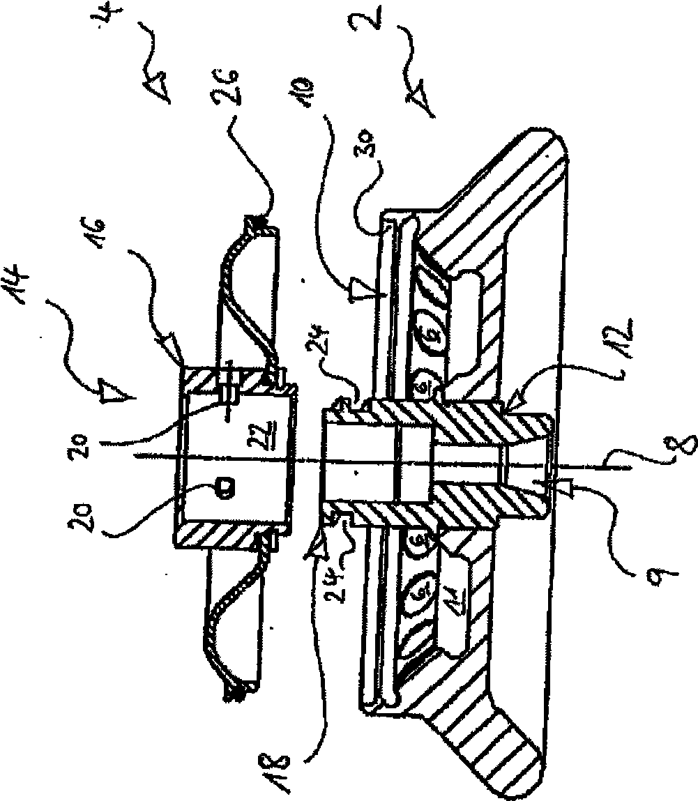
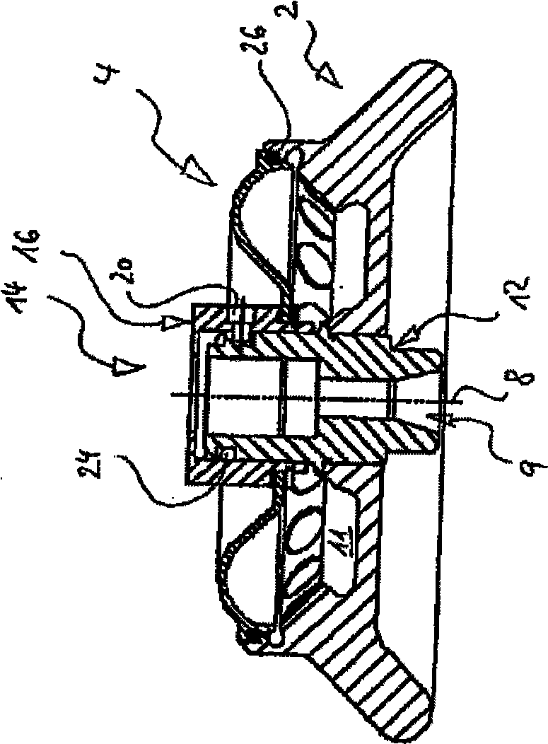
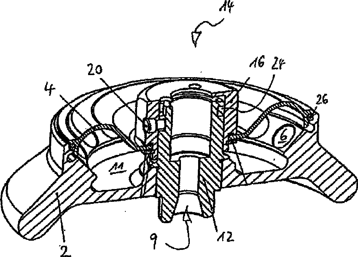
[0015] figure 1 A centrifuge rotor 2 is disclosed and a cover 4 is depicted being placed on the centrifuge rotor 2 by a user's hand (not shown). The centrifuge rotor 2 has a row of holes or compartments 6 evenly distributed around the periphery of the rotor, into which test tubes (not shown) inclined outwardly at the bottom can be inserted. Overall, the rotor is rotationally symmetrical about a vertical axis 8 and has in the center a vertical central hole 9 through which the rotor 2 can be inserted onto a centrifuge drive shaft (not shown in the figures) Centrifuge.
[0016] The compartment 6 is accessible for the test tubes through a large circular opening 10 at the top of the rotor 2 . They are situated on the radially outer wall of a bowl-shaped chamber 11 which extends annularly around a central axis 12 .
[0017] Arranged on the bottom side of the shaft 12 is the hole 9 for the drive shaft of the centrifuge rotor. Towards the top, the shaft 12 projects cylindrically t...
PUM
 Abstract
Description
Claims
Application Information