Centrifuge for the purification of lubricating oil of an internal-combustion engine

a technology for internal combustion engines and centrifuges, which is applied in centrifuges, machines/engines, lubricant mounting/connections, etc., can solve the problem of no more lubricating oil flowing through, and achieve the effect of preventing the inflow of lubricating oil to the centrifug

Active Publication Date: 2005-01-27
HENGST WALTER
View PDF12 Cites 11 Cited by
  • Summary
  • Abstract
  • Description
  • Claims
  • Application Information

AI Technical Summary

Benefits of technology

[0005] It is achieved by the closing element in the centrifuge provided according to the invention, that the centrifuge releases the partial oil volume stream with the assembled centrifuge rotor and that the flow path for the lubricating oil is closed with the centrifuge rotor missing in the centrifuge. Thus no more lubricating oil can flow through the lateral branch of the oil circuit, in which the centrifuge is situated, with an erroneously missing centrifuge rotor, apart from small possible leakage amounts. Thus it is guaranteed that the entire lubricating oil amount is available for the lubrication of the appropriate internal-combustion engine. Filtering of the lubricating oil takes place further via the filter cartridge, which is usually present beside the centrifuge; only micro filtering through the centrifuge in the bypass flow is omitted. This missing micro filtering however does not pose an immediate danger of damage for the appropriate internal-combustion engine. Thus the operational reliability of the internal-combustion engine is ensured, even if the centrifuge rotor of the centrifuge is erroneously not assembled.
[0006] Preferably a sleeve, which is movable in the longitudinal direction of the shaft, is arranged as a closing element in the hollow inside of the shaft or on the outer circumference of the shaft, whereby the orifice opening is a lateral opening from the hollow inside of the shaft outward. Opening and closing of the orifice opening then take place simply via axial shifting of the sleeve either away from the orifice opening or over the orifice opening. Thereby a particularly simple design is achieved, which requires only a low additional manufacturing expenditure compared to a conventional centrifuge.
[0015] The invention suggests further that a pedestal part of the housing supporting the shaft serves for the limitation of the shift path of the sleeve in its opening direction. For this design no special component is required for the limitation of the shift path of the sleeve in its opening direction, which keeps production costs low.
[0018] In order to protect the centrifuge and its centrifuge rotor from damage by a too high lubricating oil pressure, the invention suggests a design that with the centrifuge rotor inserted into the housing, the closing element is movable in a closing direction against a preloading force working in its opening direction by a force which is created by a lubricating oil pressure above a preset upper lubricating oil limiting pressure. Hereby it is achieved that with a reaching or exceeding of an upper lubricating oil limiting pressure, the closing element is transferred by the lubricating oil into its closing position, whereby a further inflow from lubricating oil to the centrifuge is prevented. Thus it is safely eliminated that too large and harmful lubricating oil pressures can occur within the area of the centrifuge.
[0019] In a further embodiment of the design of the centrifuge described before, it is intended that at least one spring is provided between the bottom of the centrifuge rotor and the closing element, that the spring preloads the closing element with a force aiming in its opening direction and that the closing element is movable in the closing direction against the force of this spring which is created by the force of the upper lubricating oil limiting pressure. The generation of the preloading force by a spring is technically simple and reliable. Additionally a desired lubricating oil limiting pressure can be defined trouble-free by selection of suitable spring characteristic values, at which the closing element shuts off the oil flow through the centrifuge.

Problems solved by technology

Thus no more lubricating oil can flow through the lateral branch of the oil circuit, in which the centrifuge is situated, with an erroneously missing centrifuge rotor, apart from small possible leakage amounts.

Method used


Image

  • Centrifuge for the purification of lubricating oil of an internal-combustion engine
  • Centrifuge for the purification of lubricating oil of an internal-combustion engine
  • Centrifuge for the purification of lubricating oil of an internal-combustion engine

Examples


Embodiment Construction

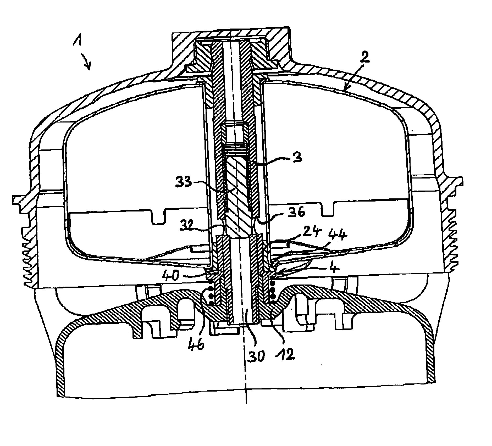
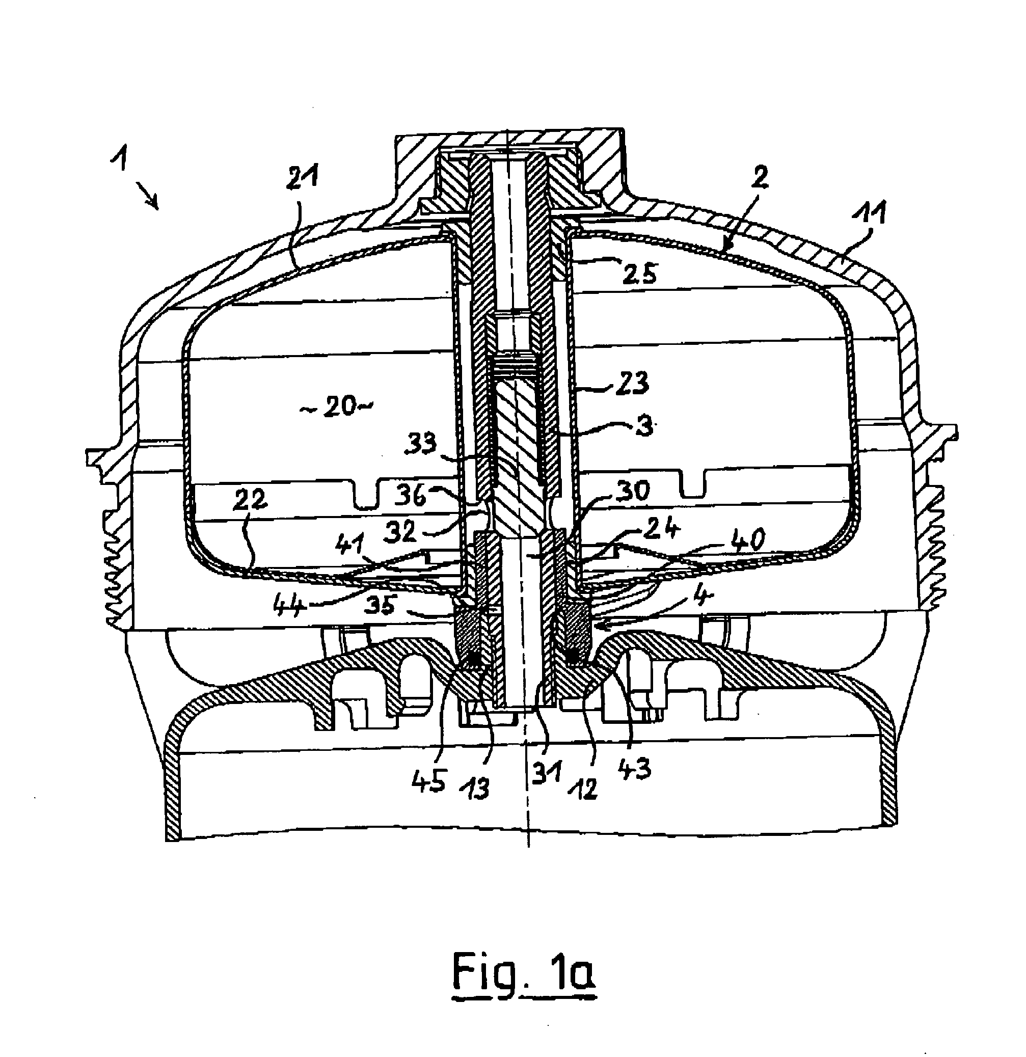
[0027]FIG. 1a of the drawing shows a first centrifuge 1, which is a part of a purification setting for the lubricating oil of an internal-combustion engine. Besides the centrifuge 1 the purification setting comprises an oil filter with a filter cartridge here not represented, which is located beneath the centrifuge 1. The filter cartridge is located in the main flow of the oil system; a partial flow of it, in the order of magnitude of approximately 10%, is usually branched off after the filtering by the filter cartridge and piped for the separation of finest dirt particles through the centrifuge 1. The lubricating oil coming from the filter cartridge flows during the operation of the internal-combustion engine through the hollow inside 30 of a shaft 3, which is arranged housing-fixed underneath a removable cover 11. The cover 11 is a part of the centrifuge housing, which is in all other respects not represented. A centrifuge rotor 2 is rotatably mounted on the shaft 3 by means of tw...


PUM

PropertyMeasurementUnit
pressureaaaaaaaaaa
pressureaaaaaaaaaa
outer circumferenceaaaaaaaaaa

Abstract

A centrifuge for the purification of lubricating oil of an internal-combustion engine is provided which includes a housing with a removable cover, a housing-fixed shaft arranged in the housing and a centrifuge rotor which is rotatably mounted on the shaft and is replaceable. The shaft is hollow at least in its lower part and forms in its hollow inside a section of a lubricating oil supply canal, which canal is in flow connection with an inside of the centrifuge rotor mounted on the shaft over at least one orifice opening. The centrifuge also includes an adjustable valve plug arranged at the shaft and arranged to be held in an open position by the centrifuge rotor. The valve plug releases the orifice opening in the open position. The valve plug is also arranged to be transferred into a closing position and held in the closing position by a force created by at least one of a pressure of the lubricating oil and by a preloading component if the centrifuge rotor is missing. The valve plug plugs the orifice opening in the closing position.

Description

BACKGROUND OF THE INVENTION [0001] The present invention relates to a centrifuge for the purification of lubricating oil of an internal-combustion engine, with a housing with a removable cover, with a housing-fixed shaft arranged in the housing and with a centrifuge rotor, which is rotatably mounted on the shaft and is replaceable, whereby the shaft is hollow at least in its lower part and forms in its hollow inside a section of a lubricating oil supply canal, which is in flow connection with the inside of the centrifuge rotor mounted on the shaft over at least one orifice opening. [0002] Centrifuges of the type initially specified are usually used as partial flow filters beside a filter cartridge. Thereby usually only a partial oil volume stream flows over the centrifuge, which is approximately 10% of the entire oil flow, which flows through the filter cartridge. In order to keep flow resistances low, the lubricating oil supply canal to the centrifuge is usually designed with a lar...

Claims


Application Information

Patent Timeline
Patent Type & Authority Applications(United States)
IPC IPC(8): B04B5/00B04B9/12C10M175/00F01M11/03
CPCB04B5/005B04B9/12F01M2001/1085F01M11/03F01M2001/1035C10M175/0058
Inventor GROSSE-WIESMANN, KARL
Owner HENGST WALTER
Why Eureka
Try Eureka